About the client and the project
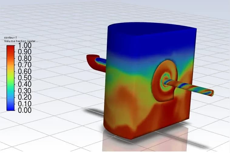
Sel Environmental engaged us, on a stormwater project in Leeds, UK, to design and simulate a family of radial vortex flow control (VFC) devices. These units control stormwater with a purely hydraulic mechanism, with no moving parts, no power and no control system: at low flows the water passes freely, and as the flow rises a vortex forms inside the unit and throttles the discharge.
The brief had two parts:
We ran the work in two phases: first a validated baseline design, then a full product range with the predictive capability for future custom units.
The challenge
Stormwater flow controls have to work across a wide range of conditions, and the client's requirements were demanding:
On top of that, the design needed a cross-sectional area 3 to 6 times larger than a traditional orifice plate, with large internal openings to reduce clogging. The flow had to be simulated and visualised, especially around the kickback and flushing thresholds, and the final deliverable was a locked Excel calculator giving the numbers and performance curves for each size.
Our approach
Start from a proven geometry
We began with an existing 350 mm cowl and optimised the 100 mm outlet version (Unit 3) first, then scaled the other sizes with fixed relationships between the outlet diameter, swirl chamber width, inlet height and overall swirl diameter.
Simulate the full head range
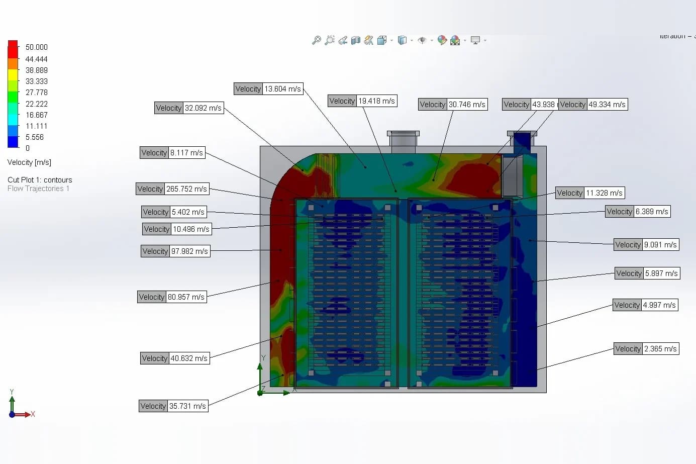
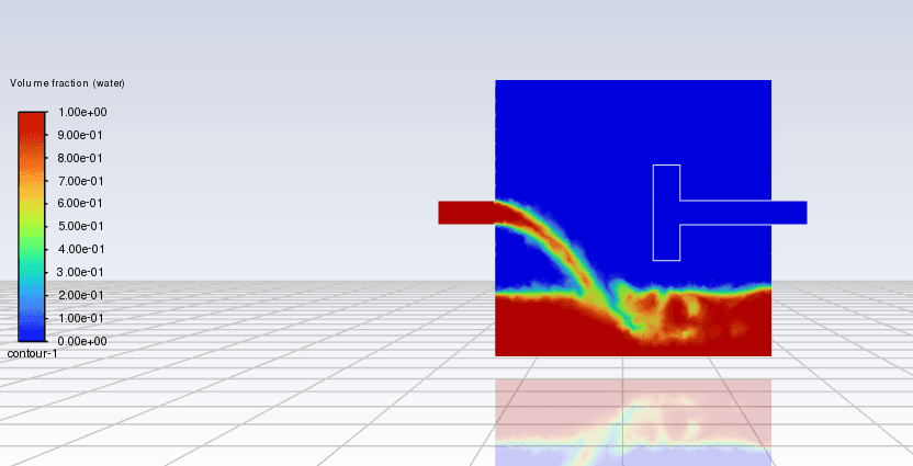
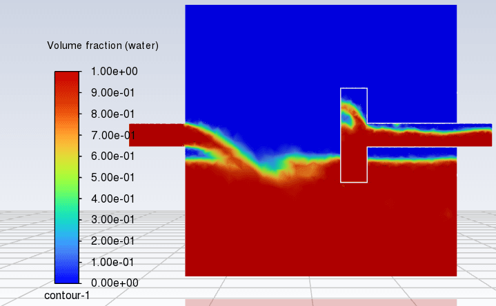
Transient multiphase CFD on a fine mesh followed the water and air at heads from 0.1 to 2.5 m, around a design head of 0.77 m, tracking how the vortex forms, the pressure differences and the flow regimes.
Tune the hydraulics
We set the kickback point so the flow throttles only at the design head, adjusted "Area A" to keep a vertical rise in flow and avoid premature bypassing, and added a buoyancy-driven emergency flushing path that opens when a blockage threatens the main outlet, clearing the debris on its own.
Build the sizing tool
Correlations derived from the CFD results became an Excel model that sizes a unit from any design head and flow.
Inside the vortex
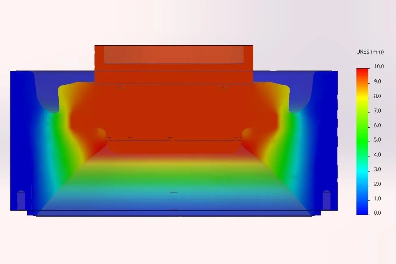
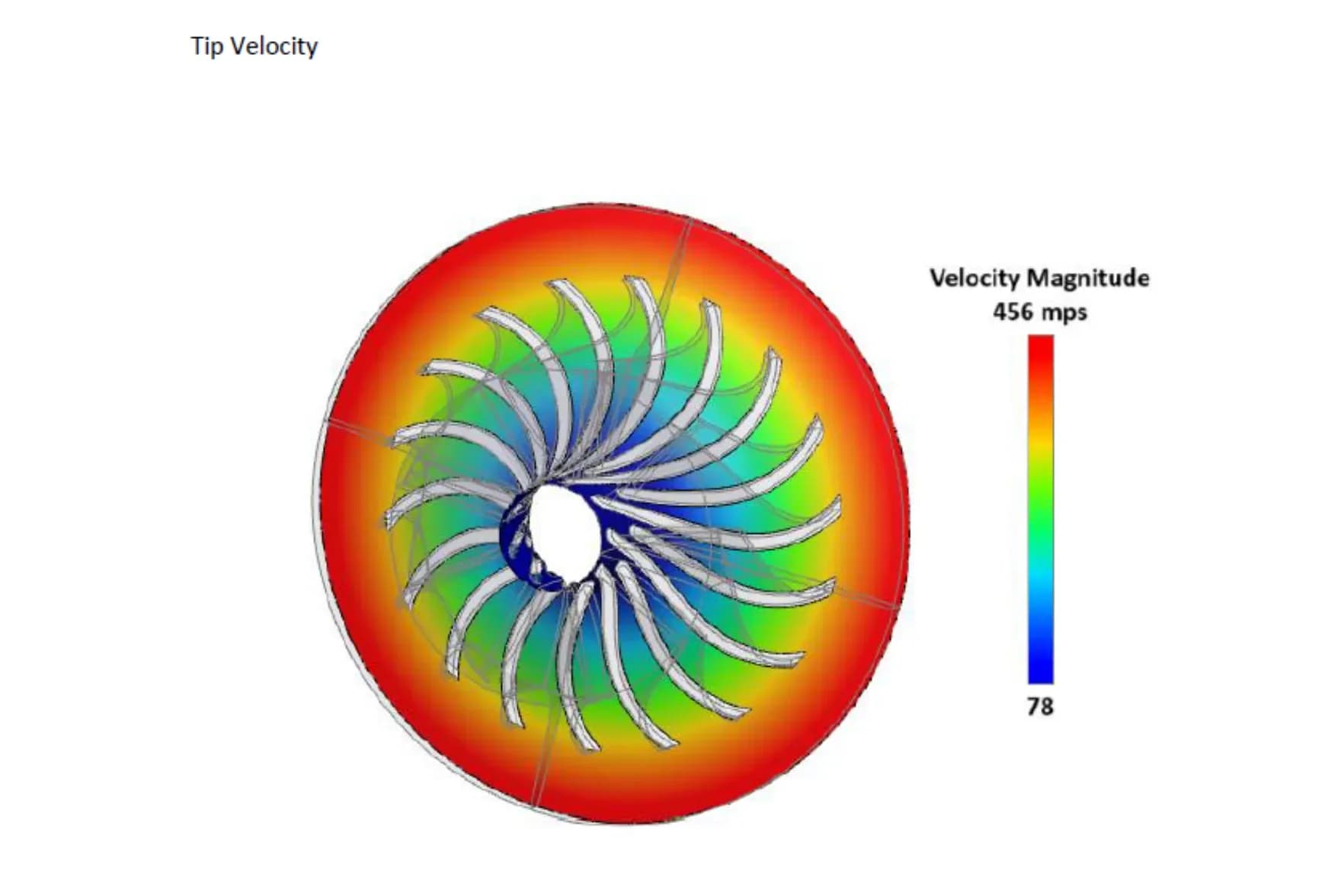
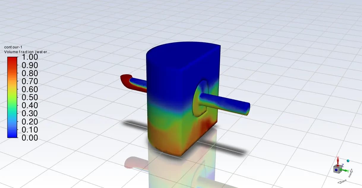
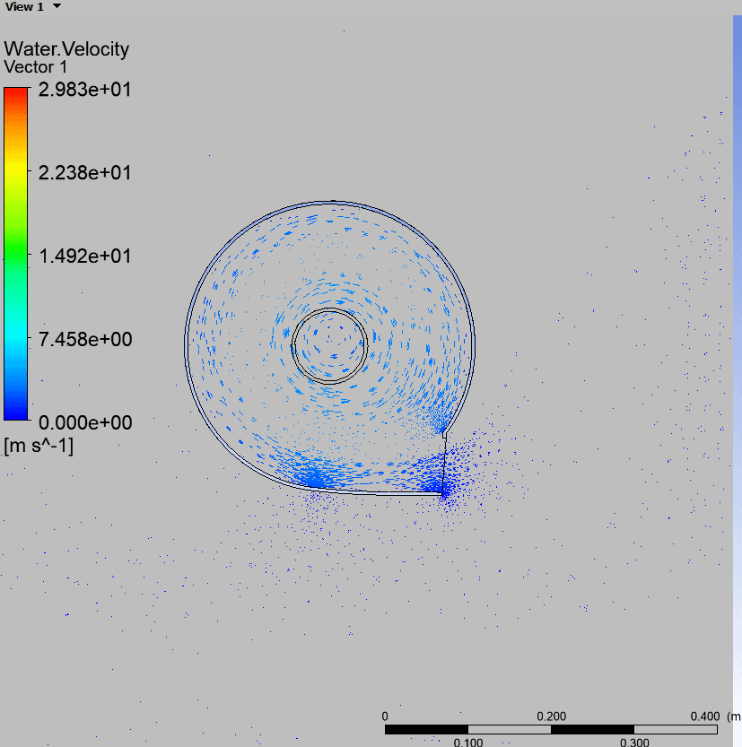
The simulations showed the vortex forming rapidly, with a well-developed air core and high back-pressure at the centre: the mechanism that throttles the flow without moving parts. The flow was rotationally symmetric, with strong swirl and minimal dead zones.
Results
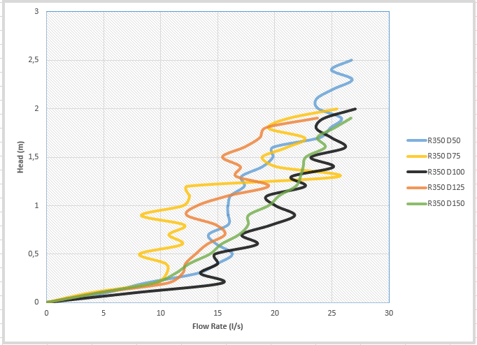
The CFD produced head–discharge curves for all five unit sizes, the basis of the sizing tool:
Installation and maintenance were designed in from the start: custom-fit housings, no moving components, easy access through standard rodding points, and 316L stainless steel to resist chemical attack and abrasion.
The sizing tool
Alongside the CFD, we built an Excel model from empirical correlations derived from the CFD results. Enter a design head and flow, and it returns:
New VFC designs can now be generated and quoted quickly, with simulation-backed accuracy.
Conclusion
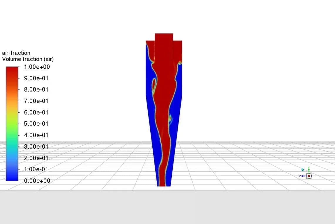
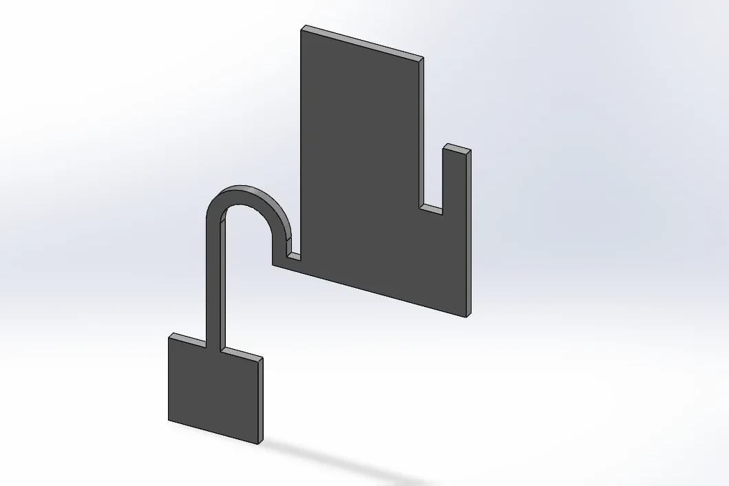
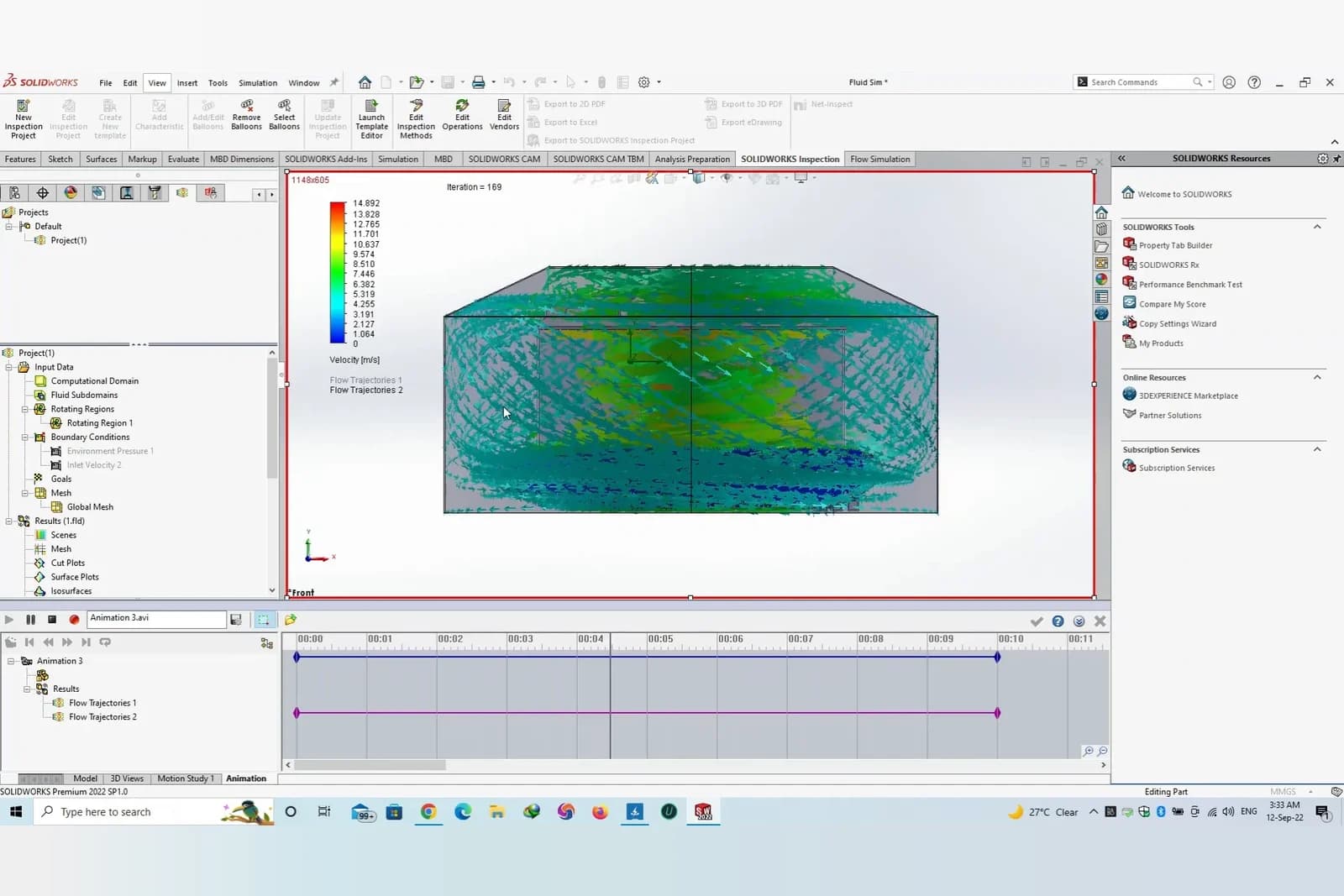
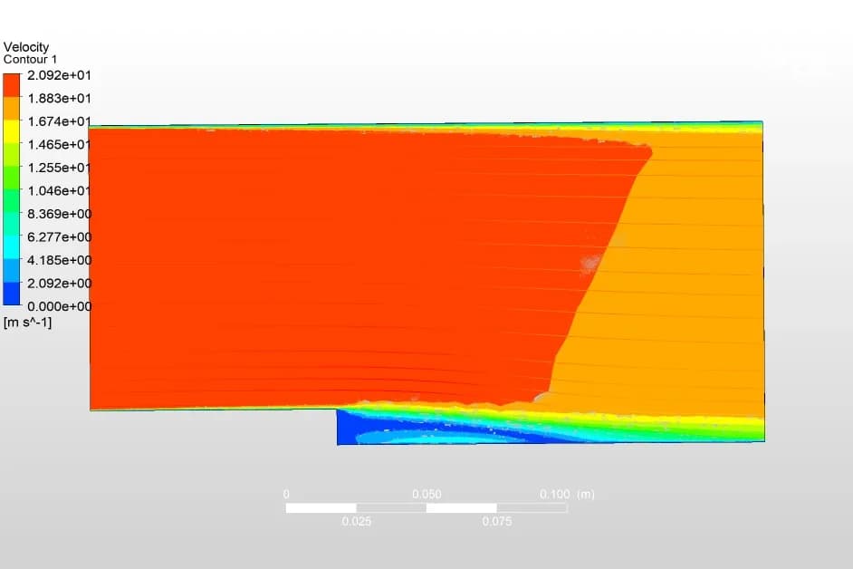
The LR3 series of radial vortex flow controls now has a validated, optimised geometry, reliable throttling across a wide head range, self-maintaining flow and a user-friendly tool for design and quoting. Beyond a high-performing product family, Sel Environmental has a repeatable design and quoting system for future applications, with physical prototyping, field testing and further head and flow combinations as the next steps. We used the same multiphase CFD to capture the air core in a cyclone separator and the siphon in a self-draining water tank.
Frequently asked questions
What is a vortex flow control device?
A stormwater throttle with no moving parts. At low flows the water passes freely; as the head rises, a vortex forms inside the chamber and its back-pressure limits the discharge. Because it throttles with a vortex rather than a small hole, its openings are much larger than an orifice plate's, so it is less likely to block.
Why use CFD to design a vortex flow control?
The throttling depends on how the vortex and its air core form, and on where the flow kicks back. Multiphase CFD shows this at every head (from 0.1 to 2.5 m here), so the geometry can be tuned before any prototype is made.
How were the five unit sizes designed?
We optimised the 100 mm outlet unit from a 350 mm cowl first, then scaled the 50, 75, 125 and 150 mm units with fixed relationships between the outlet diameter, swirl chamber width, inlet height and swirl diameter.
What does the Excel sizing tool do?
Built on correlations from the CFD, it takes a design head and flow and returns the inlet size, orifice diameter, manufacturing specifications, a head–discharge curve and table, and the minimum sump depth, pipe diameter and clearances.