
Home / Projects / Multiphase CFD Analysis of a Cyclone Separator to Predict the Air Core
Multiphase CFD Analysis of a Cyclone Separator to Predict the Air Core
Project Summary
A cyclone separator has no moving parts. It does its job purely with swirl, spinning the incoming mixture so hard that the heavier phase is thrown to the wall and drops out of the bottom while the lighter phase leaves through the top. What decides whether it works well is a column of air that forms down the middle of the spinning flow, known as the air core. We ran a multiphase computational fluid dynamics (CFD) analysis in Ansys Fluent to capture that air core and see how the separator behaves inside.
The air core is not a detail that can be ignored. Its size and stability control how the flow splits between the overflow at the top and the underflow at the bottom, and that split is what sets the separation efficiency of the whole device. You cannot see it from the outside of a running unit, and a hand calculation will not give it to you. A properly built multiphase model shows it directly, which is why this simulation is the fastest honest way to judge a cyclone design before it is built.
Objectives and Approach
The purpose of the study was to see inside the separator and judge the design from the flow physics rather than from rules of thumb. The objectives for the CFD analysis were:
- Capture the air core along the axis of the cyclone and show how far it runs from the top of the unit down towards the outlet.
- Resolve the interface between the air and the liquid, since a smeared interface would give a false picture of the core.
- Understand the swirling flow field that throws the heavy phase to the wall, because that is the mechanism the separation depends on.
- Give the client a clear basis for judging the geometry, including the vortex finder and the conical section, before committing to a build.
The separator was modelled in Ansys Fluent as a multiphase problem using the Volume of Fluid (VOF) approach, which tracks the boundary between the air and the liquid instead of blurring them together. That is the standard and proven way to reproduce an air core. The mesh was refined along the axis where the core forms and near the walls where the swirl is strongest, so both the core and the rotating flow around it would be resolved properly.
Simulation Setup and Boundary Conditions
A cyclone is a demanding CFD problem, because the flow is strongly swirling and two phases have to be tracked at once. The setup reflected that:
- Multiphase model: Volume of Fluid, solving the air volume fraction so the air core and its interface with the liquid come out of the solution rather than being assumed.
- Turbulence: a model suited to highly swirling flow, since simpler two-equation models struggle with the strong rotation inside a cyclone and tend to wash the core out.
- Inlet: the feed introduced tangentially at its operating flow rate, which is what generates the swirl in the first place.
- Outlets: the overflow at the top through the vortex finder and the underflow at the bottom, both open to the surrounding pressure so the air can be drawn in and the flow can split naturally.
- Mesh: refined along the central axis and through the conical section to hold the core sharp and capture the tangential velocity gradients that drive separation.
The solution was run until the air core had formed and settled into a steady shape rather than still growing, because a core that is still developing would give misleading numbers for the flow split.
Results and Findings
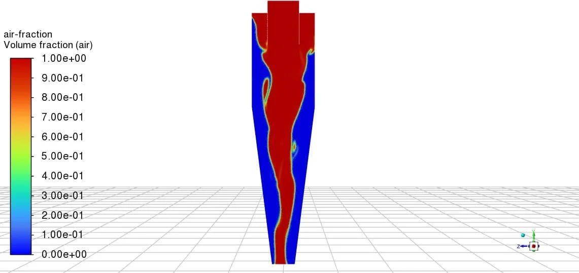
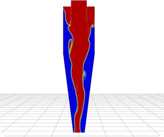
The air volume fraction result, shown above, is the clearest picture of what is happening inside. Red marks pure air and blue marks pure liquid, and the model produced a continuous air core running the full height of the separator, from the top section all the way down through the cone to the outlet. That is exactly the behaviour a working cyclone should show, and the fact that the core reaches right through confirms the swirl is strong enough to sustain it end to end.
The interface between the air and the liquid comes out sharp and well defined, with only a thin transition band between the two phases instead of a wide smeared zone. That matters more than it might look. A crisp interface means the VOF model and the mesh are doing their job, so the core diameter can be trusted, and the core diameter is what governs how much flow leaves through the overflow versus the underflow. The liquid is held in an annular layer against the wall all the way down, which is the pattern that lets the heavier phase be carried to the underflow.
The core is not perfectly straight, and that is worth noting rather than glossing over. It wanders slightly and shows some waviness along its length, which is normal and physically real in a cyclone, since the core precesses around the axis rather than standing perfectly still. A core that stayed pin-straight in a simulation would be more suspicious than this one. What matters for the design is that it stays continuous and does not collapse or pinch off partway down, and it does not.
For the client, this gives a solid baseline. The separator generates a stable, full-length air core at the operating condition, so the geometry is fundamentally sound. From here the model can be used to test changes cheaply, such as adjusting the vortex finder depth, altering the cone angle, or varying the feed rate, and see straight away how the core diameter and the flow split respond, which is the practical route to improving separation efficiency without building and testing one unit after another.
Multiphase CFD at Solvo Engineers
Cyclones, hydrocyclones, and separators are used everywhere from mineral processing and oil and gas to water treatment and food production, and they all live on the same physics: swirl, an air core, and a flow split that decides how well the device performs. Because none of that can be seen from outside a running unit, multiphase CFD is the practical way to understand it, whether the goal is to size a new separator or work out why an existing one is not separating as well as it should.
At Solvo Engineers we build multiphase computational fluid dynamics models in Ansys Fluent and STAR-CCM+ for separators, tanks, mixers, and free-surface flows, covering air cores, phase separation, and flow splits, alongside our wider CFD and FEA consulting work. If you have a separator or any multiphase flow problem you need to understand or improve, our team can help. Reach out through our contact page and talk it through with a CFD engineer.
Related articles
Our Projects
See how Solvo Engineers has helped its clients achieve their vision of digital innovation.

Our Technologies
 Contact Us
Get in touch with us