
Home / Projects / FEA of a 48V-100Ah Battery Module Frame for Structural Strength
FEA of a 48V-100Ah Battery Module Frame for Structural Strength
Project Summary
A client asked us to confirm that the frame of their 48V-100Ah battery module was strong enough before they committed to production. The frame carries the full weight of the module and holds it in place, so any weak spot in it puts the cells, the wiring and the surrounding equipment at risk. We ran a static structural finite element analysis (FEA) in Ansys to see exactly how the frame behaves under load, where the stress builds up, and whether the design has enough margin against failure.
Instead of building a physical prototype and hoping it holds, the goal was to catch problems on screen first. We built a detailed model of the frame, applied the loads it sees in service, and looked at three things that tell us whether a structure is safe: how far it deflects, how high the stresses climb and the safety factor across the part. The analysis gave a clear answer on structural strength and just as usefully, showed the client the one area that needed reinforcement before the frame was ready to manufacture.
Objectives and Approach
The main question was simple: can this frame carry the 48V-100Ah module safely, and if not, where does it need help? To answer it, we set a few clear objectives for the finite element analysis.
- Confirm that the frame holds the weight of the fully assembled module without bending or deflecting more than the design allows.
- Find the exact locations where stress concentrates, since those are the spots most likely to crack or yield first.
- Check the safety factor across the whole frame against the yield strength of the material, so we know how much real margin the design has.
- Flag any area that falls short of the strength target and recommend a practical fix before the frame goes into production.
We started from the frame geometry and built a clean finite element model in Ansys. The mesh was refined around the mounting brackets, weld lines, bolt holes and cut-out edges, because those transitions are where stress tends to spike and a coarse mesh would miss the peak. The module was fixed at its real mounting points, and the load was applied the way the frame actually carries it in service. That gave us a model that reflects the real part rather than an idealised version of it.
Simulation Setup and Loading Conditions
The study was set up as a static structural analysis in Ansys, which is the right tool for checking whether a load-bearing part can hold a steady load without yielding. The setup covered the following.
- The frame material was defined with its elastic properties and yield strength, so the results could be compared directly against the point where the metal would start to deform permanently.
- The load represented the weight of the 48V-100Ah module supported by the frame, together with the everyday operating and handling loads the enclosure has to take.
- Fixed constraints were applied at the bolt and bracket locations where the frame attaches to its mounting surface, matching how the real assembly is held down.
- The mesh was kept fine in the high-stress regions near the base, the brackets, and the openings, and a convergence check made sure the peak stress had settled rather than being an artefact of a coarse mesh.
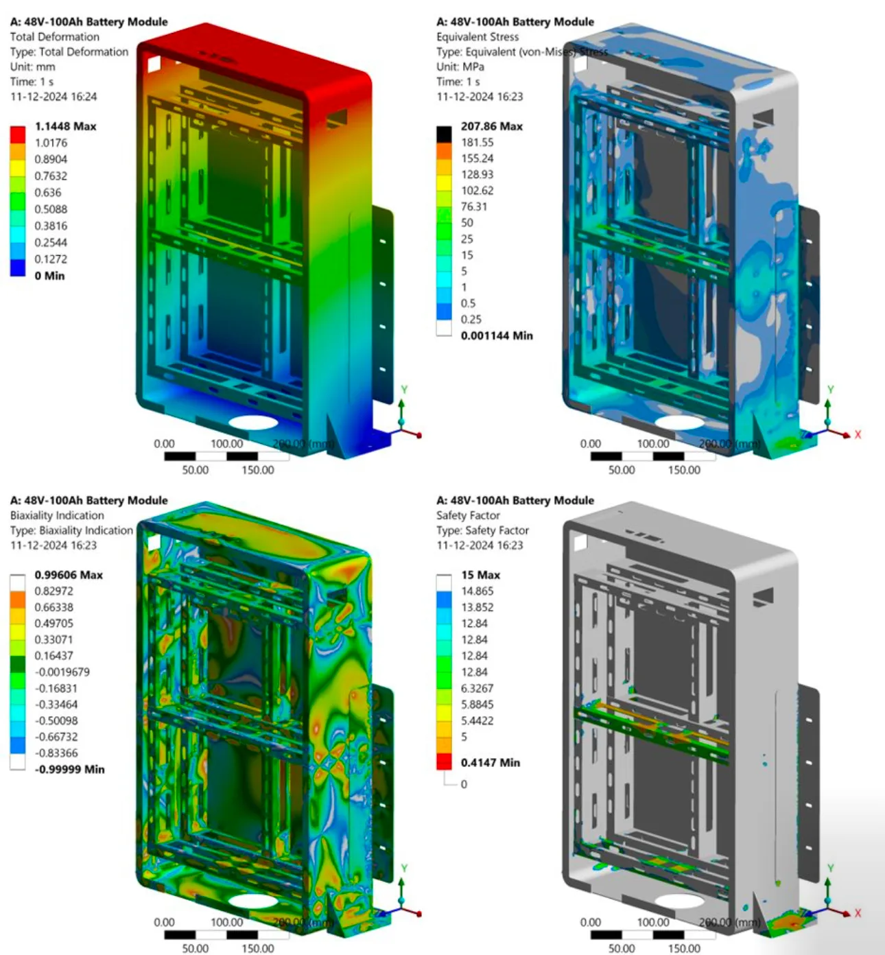
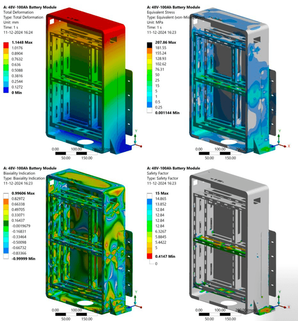
With the model set up this way, the results give a realistic picture of how the frame responds to load. Four outputs were pulled from the solution to judge the design: total deformation, equivalent (von Mises) stress, biaxiality indication, and safety factor. Together these show how much the frame moves, how hard it is working, and where the real risk sits.
Results and Findings
The frame performed well across most of its structure, but the analysis found one area that needs attention before production. Here is what the results showed.
Total deformation reached a maximum of about 1.14 mm at the upper part of the frame, farthest from the mounting points. For an enclosure of this size that amount of movement is small and sits well within a sensible stiffness limit, so the frame is not too flexible in normal use. The equivalent von Mises stress peaked at roughly 208 MPa, and that peak was not spread evenly. It sat in a small region near the lower mounting area, exactly where you would expect load to funnel as it passes from the module, through the frame, and into the bolts.
The safety factor plot told the most important part of the story. Across the bulk of the frame the safety factor was high, comfortably above the target, which means most of the structure carries its load with plenty of margin. In one small spot at the mounting base, though, the minimum safety factor dropped to about 0.41. A value below 1 means the material at that point would be pushed past its yield strength under the applied load, so that region is a genuine weak point rather than a rounding issue. The biaxiality result in the same area pointed to a demanding, multi-directional stress state that a fatigue or vibration check would want to look at more closely.
The fix here is straightforward and local. Reinforcing that mounting region, by adding a gusset or a stiffening rib, increasing the material thickness in that zone, or easing the sharp transition that drives the stress, lifts the safety factor back above the target without adding much weight or cost to the rest of the frame. Because the analysis pinpointed the exact spot, the client could make a small, targeted change instead of over-building the whole enclosure, and then move to production knowing the frame will hold the module safely.
Structural FEA for Battery Systems at Solvo Engineers
Battery module frames and enclosures sit at the heart of every energy storage and electric vehicle system, and they have to stay strong through weight, vibration, shock, and years of service. A finite element analysis catches a weak mounting point or an over-stressed bracket while it is still a line on a screen, long before it turns into a warranty claim or a safety problem in the field. Finding that one region on this 48V-100Ah frame, and fixing it with a small local change, shows how much a single FEA study can save compared with discovering the same issue after tooling is cut.
At Solvo Engineers we run this kind of structural FEA in Ansys every day, from single brackets and battery frames to full enclosures and load-bearing assemblies, and we back it up with CFD and thermal work when a design needs both strength and cooling. If you are developing a battery module, an enclosure, or any structural part and want to know whether it will hold up before you build it, our team can help. Reach out through our contact page to talk through your project with a CAE engineer.
Related articles
Our Projects
See how Solvo Engineers has helped its clients achieve their vision of digital innovation.

Our Technologies
 Contact Us
Get in touch with us