
Home / Projects / CFD Airflow Analysis of a Fan Heater Using Ansys CFX
CFD Airflow Analysis of a Fan Heater Using Ansys CFX
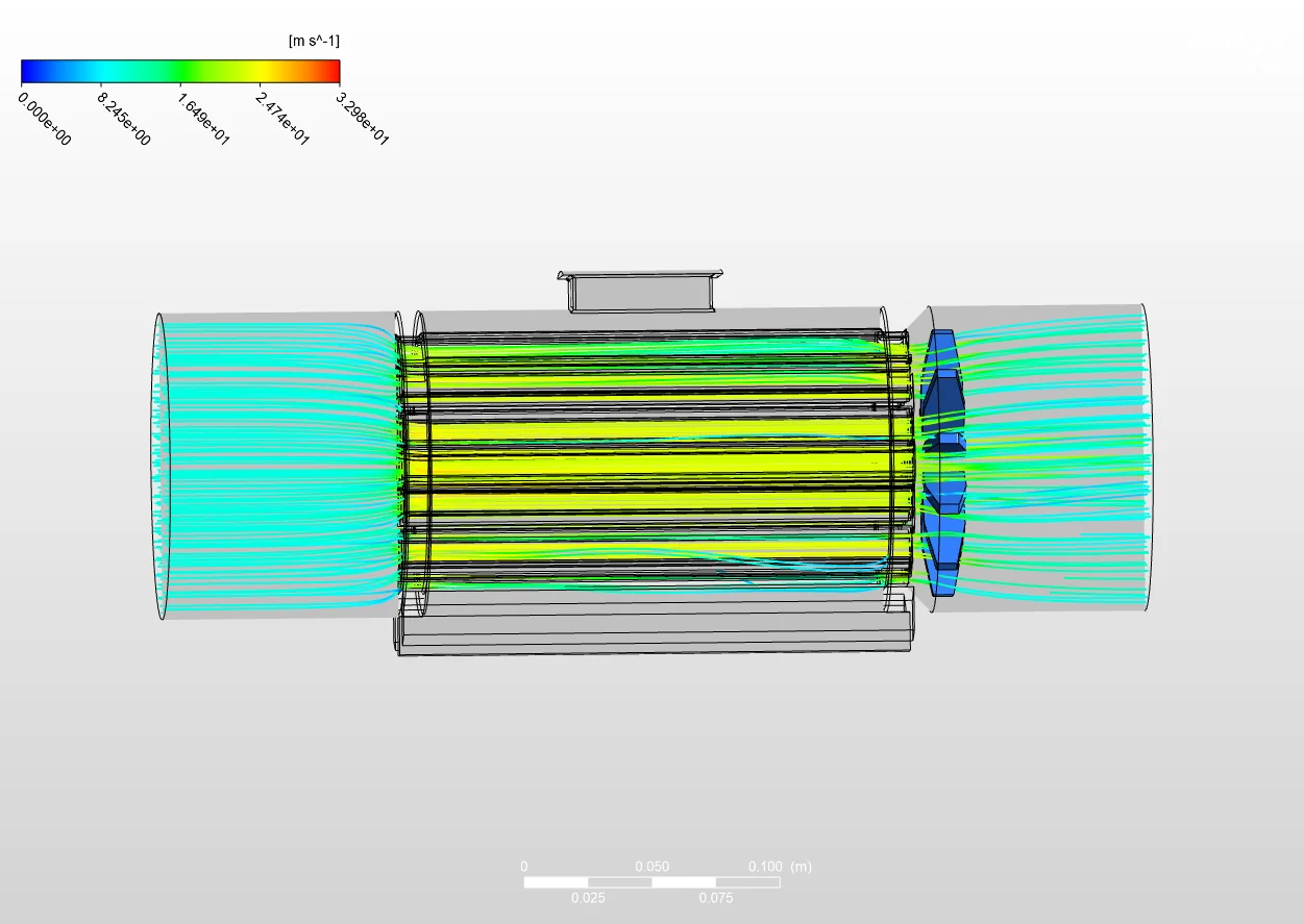
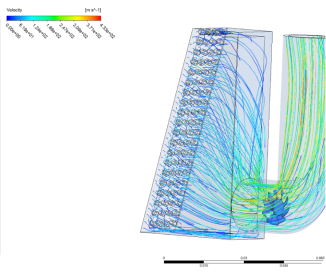
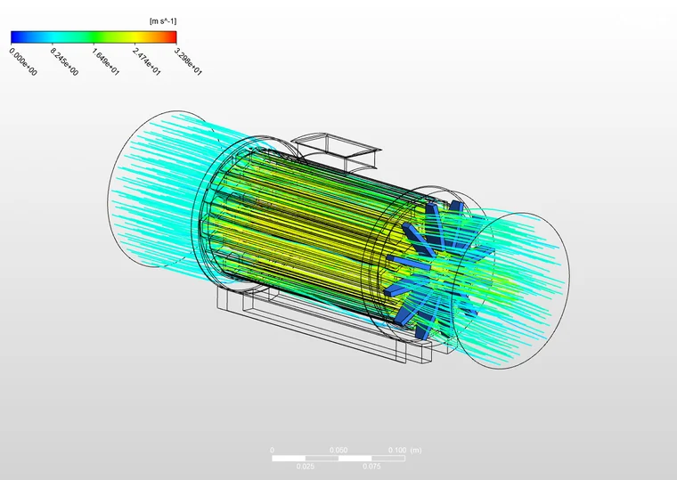
A fan heater is only as good as the air it can push. This project uses CFD in Ansys CFX to look inside the unit and trace how air moves through it, drawn in at one end, driven through the core past the fan, and pushed out at the outlet. Velocity streamlines make the whole flow path visible, so the airflow can be judged where it matters most, at the outlet where the air leaves the unit.
The streamlines are coloured by air speed, from the slow incoming flow through to the fastest flow inside the unit, which reaches around 33 m/s. Following them from inlet to outlet shows where the air speeds up, how evenly it passes through the core, and how it behaves as it exits, which together tell you how well the unit is moving air.
Objectives
The aim was to understand the airflow through the fan heater and judge how it performs at the outlet. The objectives were:
- Trace the airflow through the fan heater from inlet to outlet using CFD.
- Map the air velocity through the unit and see where the flow speeds up and slows down.
- Judge the airflow at the outlet, where the air leaves the unit.
- Build a CFD model that can test design changes to the fan or internals before any hardware is built.
CFD Setup
The airflow was solved in Ansys CFX. The fan heater geometry, with its inlet, internal fan and components, and outlet, was placed inside a flow domain so the air could be tracked as it moved through and around the unit. The setup was:
- Tool: Ansys CFX, solving the airflow through the full unit.
- Domain: the fan heater with the flow region extended at the inlet and outlet so the incoming and leaving air are both captured.
- Outputs: velocity streamlines and the air speed field from inlet to outlet.
Airflow Through the Unit
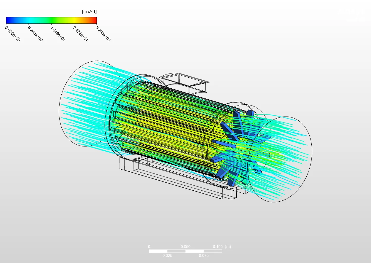
Seen from an angle, the streamlines show the air being pulled in across the full inlet face and drawn into the core of the unit. Inside, the flow tightens and speeds up as it passes the fan and the internal components, reaching its highest velocity through the middle of the unit. The angled view makes it clear that the air is filling the whole cross section rather than slipping through one side, which is what you want for a unit that has to move air evenly.
Outlet Performance
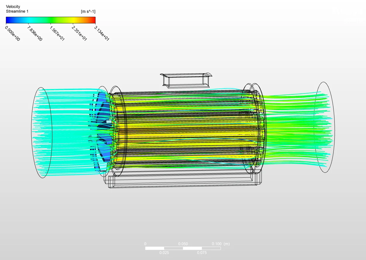
The side view focuses on how the air leaves. The streamlines carry through the core at their peak speed and then exit through the outlet, spreading out as they go. Reading the flow at the outlet is the real test of the unit, since it shows whether the air comes out with enough speed and how it is spread across the exit. This is the information you need to say whether the fan heater is actually delivering the airflow it is meant to.
Conclusion
The CFD gives a clear, complete picture of the airflow through the fan heater. The velocity streamlines trace the air from the inlet, through the core where it reaches around 33 m/s, and out at the outlet, showing both how fast the air moves and how evenly it flows. That is enough to judge the unit's airflow performance and to test changes to the fan or the internal layout in CFD before committing to hardware.
Airflow and Thermal CFD at Solvo Engineers
Getting airflow right is the difference between a product that performs and one that runs hot or weak. CFD shows the velocity, the flow path, and the outlet behaviour that decide how well a unit moves air, long before a prototype is built.
At Solvo Engineers we run airflow and thermal CFD in Ansys CFX, Ansys Fluent, and SolidWorks Flow Simulation for fans, heaters, enclosures, electronics cooling, and ducting, covering velocity and pressure fields, flow rate, and outlet performance. If you are developing a product that has to move or manage air and want to know how it performs before building it, our team can help. Reach out through our contact page and talk it through with a CFD engineer.
Related articles
Our Projects
See how Solvo Engineers has helped its clients achieve their vision of digital innovation.

Our Technologies
 Contact Us
Get in touch with us