
Home / Projects / CFD of a Converging-Diverging Nozzle: Choked Flow, Shocks and Expansion Waves
CFD of a Converging-Diverging Nozzle: Choked Flow, Shocks and Expansion Waves
A converging-diverging nozzle is the classic piece of gas dynamics. Feed it enough pressure and the flow chokes at the throat, reaches the speed of sound, and then keeps accelerating to supersonic speed in the diverging section. Change the pressure at the outlet and the flow answers with shock waves or expansion waves, depending on which way you push it. This project set up a full CFD simulation of a CD nozzle in Ansys Fluent to recreate each of those flow regimes and to compare the results against classical one-dimensional hand calculations.
The whole study was run at a single fixed inlet pressure of 150,000 Pa, and only the back pressure at the outlet was changed from case to case. That is the honest way to do it, because it mirrors how a real nozzle behaves when the conditions downstream change while the supply stays the same. Five flow conditions were captured in all, from subsonic choked flow through to expansion waves outside the nozzle, giving a complete picture of how the nozzle responds.
Project Objectives
The brief was to pick a design exit Mach number above 1 and use a CD nozzle CFD simulation in Ansys Fluent to recreate a full set of gas dynamics behaviours. The objectives were:
- Recreate the subsonic choked flow condition, where the throat reaches sonic speed.
- Recreate the supersonic design condition, with the diverging section accelerating the flow beyond the speed of sound.
- Raise the back pressure enough to force a normal shock inside the diverging section of the nozzle.
- Raise the back pressure further to produce oblique shocks just outside the nozzle exit.
- Lower the back pressure to produce expansion waves outside the nozzle.
- Compare every CFD result against the theoretical one-dimensional hand calculations.
- Run all cases at the same inlet pressure, so only the back pressure varies.
Nozzle Setup and Flow Conditions
The nozzle geometry was built with a converging section, a throat, and a diverging section, then meshed and solved in Ansys Fluent with a density based, compressible solver, which is the right choice when the flow is going to cross the speed of sound and form shocks. The main settings were:
- Inlet pressure: fixed at 150,000 Pa for every single case.
- Back pressure: the one control that was changed, raised or lowered to move between the flow regimes.
- Working fluid: air treated as a compressible ideal gas, so density changes with pressure and temperature.
- Outputs: velocity, Mach number, static pressure, and temperature fields, plus velocity vectors to make the shocks and expansion fans visible.
Holding the inlet fixed and moving only the back pressure is what makes the five cases directly comparable, and it is exactly the setup the theoretical 1D analysis assumes, which matters for the comparison later on.
Choked Flow and the Supersonic Design Condition
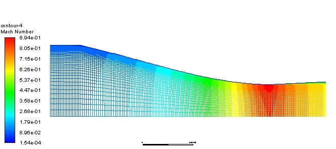
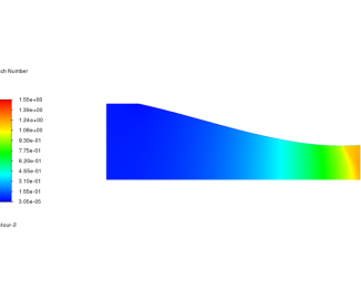
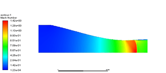
At the design condition the flow behaves exactly as a CD nozzle should. The air accelerates through the converging section, reaches sonic speed at the throat, and speeds up further in the diverging section, with the outlet velocity climbing to about 288.26 m/s in the CFD. This is the choked state: once the throat is sonic, the mass flow through the nozzle is fixed and no change downstream can increase it.
The temperature and pressure fields tell the same story from the energy side. As the flow speeds up it cools and its pressure drops, with the static temperature falling from about 299.9 K down to 258.8 K and the static pressure dropping through the diverging section. That trade of pressure and temperature for speed is the heart of how a nozzle works, and the Mach number field shown above rises steadily from the inlet towards the throat and beyond.
The clearest proof that the nozzle reaches supersonic speed is not a single number but the next three cases. Normal shocks, oblique shocks, and expansion waves simply cannot exist in subsonic flow. The fact that the nozzle produces all three, once the back pressure is set appropriately, is direct evidence that the diverging section is doing its job and pushing the flow past the speed of sound.
Shock and Expansion Wave Behaviour
With the supersonic design condition established, the back pressure was changed to walk the nozzle through three more regimes. Each one shows up clearly in the CFD.
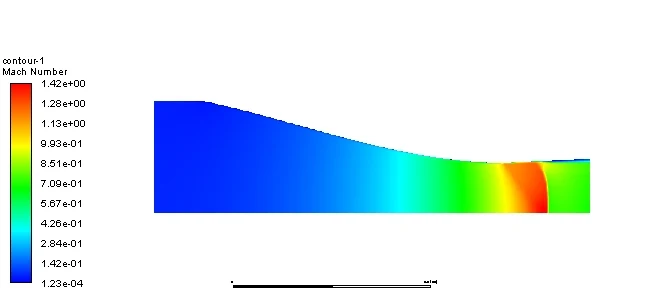
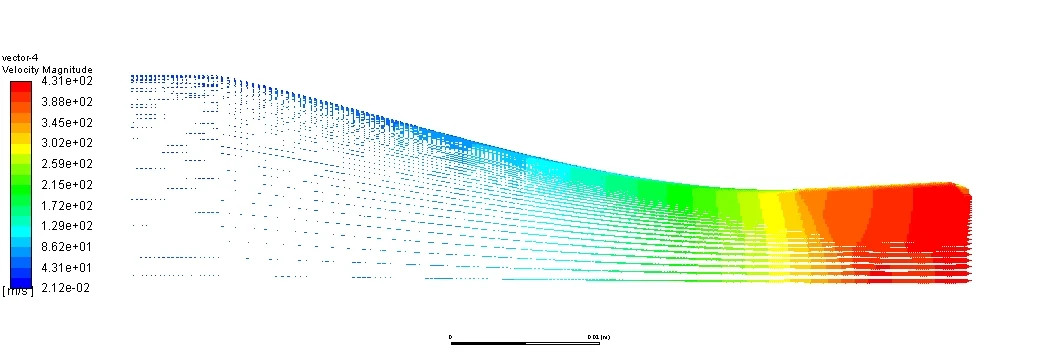
Raising the back pressure a moderate amount forces a normal shock inside the diverging section. The velocity vectors show it plainly: the flow is fast and supersonic up to a certain plane, then drops abruptly across a sharp front to a slower, subsonic speed on the other side. That sudden jump, standing straight across the nozzle, is a normal shock, and it is the nozzle adjusting the flow to meet the higher pressure demanded at the outlet.
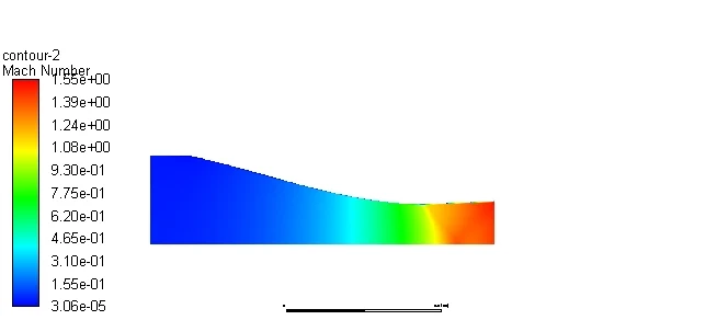
Raising the back pressure further pushes the adjustment outside the nozzle. Instead of a single normal shock inside, the flow leaves the exit still supersonic and is turned by oblique shocks that form just beyond the lip, angling back into the jet in the classic diamond pattern of an over-expanded nozzle. The flow is now doing its pressure matching in the open air rather than inside the hardware.
Going the other way and lowering the back pressure produces the opposite effect. Now the flow leaves the nozzle at a higher pressure than its surroundings, so it expands as it exits, fanning out through expansion waves outside the nozzle. This is the under-expanded case, and together with the two shock cases it completes the full set of ways a supersonic nozzle can meet the conditions outside it.
Hand Calculations and Comparison with 1D Theory
A CFD result is only trustworthy if it lines up with the theory it is supposed to reproduce, so the flow was also worked through by hand using classical one-dimensional compressible flow relations. Two of those hand calculations are shown below.
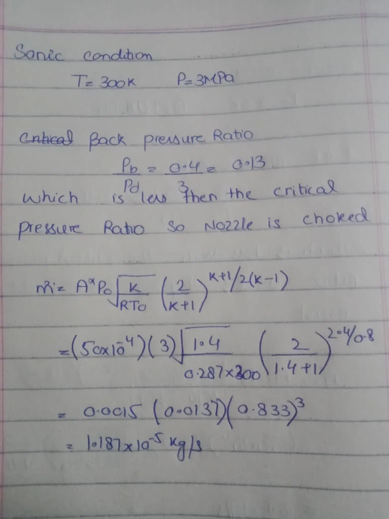
The first checks whether the nozzle is choked. Comparing the back pressure ratio against the critical pressure ratio for air confirms that the ratio is well below critical, which means the throat is sonic and the nozzle is choked, and the choked mass flow rate is then calculated from the standard mass flow relation. This is the theoretical backing for the choked behaviour the CFD shows at the throat.
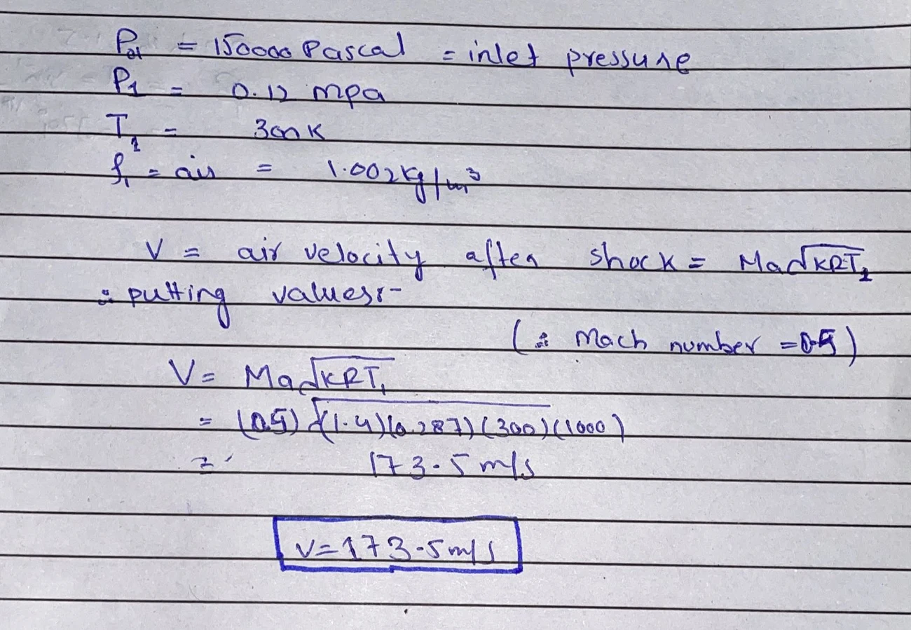
The second calculation looks at the flow behind a shock. Using the Mach number and temperature on the downstream side, the air velocity after the shock is found from the relation between velocity, Mach number, and the local speed of sound, giving about 173.5 m/s at a Mach number of 0.5. This is the theoretical counterpart to the sharp drop in velocity that the CFD shows across the normal shock, where fast supersonic flow becomes slow subsonic flow in a very short distance.
Read together, the hand calculations and the CFD tell the same physical story. The theory says the nozzle should choke and then run supersonic, and that a shock should drop the flow sharply from supersonic to subsonic; the CFD shows exactly that, and adds the full two-dimensional detail of where the shocks and expansion fans sit that a one-dimensional calculation cannot give on its own. The two approaches back each other up, which is the whole point of comparing them.
Gas Dynamics and Compressible Flow CFD at Solvo Engineers
Nozzles, diffusers, jets, and any flow that crosses the speed of sound live in the world of compressible gas dynamics, where shocks and expansion waves change the picture completely and ordinary incompressible intuition stops working. CFD, checked against one-dimensional theory the way it is here, is the tool that makes these flows visible and lets a design be judged on where its shocks sit and how much thrust or pressure recovery it really delivers.
At Solvo Engineers we run compressible and high-speed CFD in Ansys Fluent for nozzles, supersonic and transonic flows, shock behaviour, and gas dynamics problems, alongside our wider CFD and FEA consulting work. If you are designing a nozzle or working with any high-speed compressible flow and need it understood and verified before it is built, our team can help. Reach out through our contact page and talk it through with a CFD engineer.
Our Projects
See how Solvo Engineers has helped its clients achieve their vision of digital innovation.

Our Technologies
 Contact Us
Get in touch with us