Project overview
Beam brackets are critical parts of structural frames, machinery bases and mechanical linkages. If a bracket is not stiff and strong enough, the whole assembly it supports can move out of position or fail, so making sure it holds up under load is essential for product safety and performance.
In this project we ran a detailed finite element analysis (FEA) of a beam bracket in Ansys 2024 R2 under realistic boundary conditions. We calculated the total deformation, mapped the stress distribution and looked for any weak points in the geometry, to validate the design and guide further optimisation.
Objectives
Simulation setup
The bracket was analysed as a static structural problem, loaded from above and held at its base mounting holes:
| Setting | Value | Notes |
|---|---|---|
| Analysis | Static structural | In Ansys 2024 R2 |
| Mesh | Tetrahedral | Refined around the critical features |
| Load | Vertical force | Applied downwards on the top face |
| Supports | Fixed | At the base mounting holes |
| Material | Mild steel | Linear isotropic, E = 210 GPa |
Results: deformation and stress flow
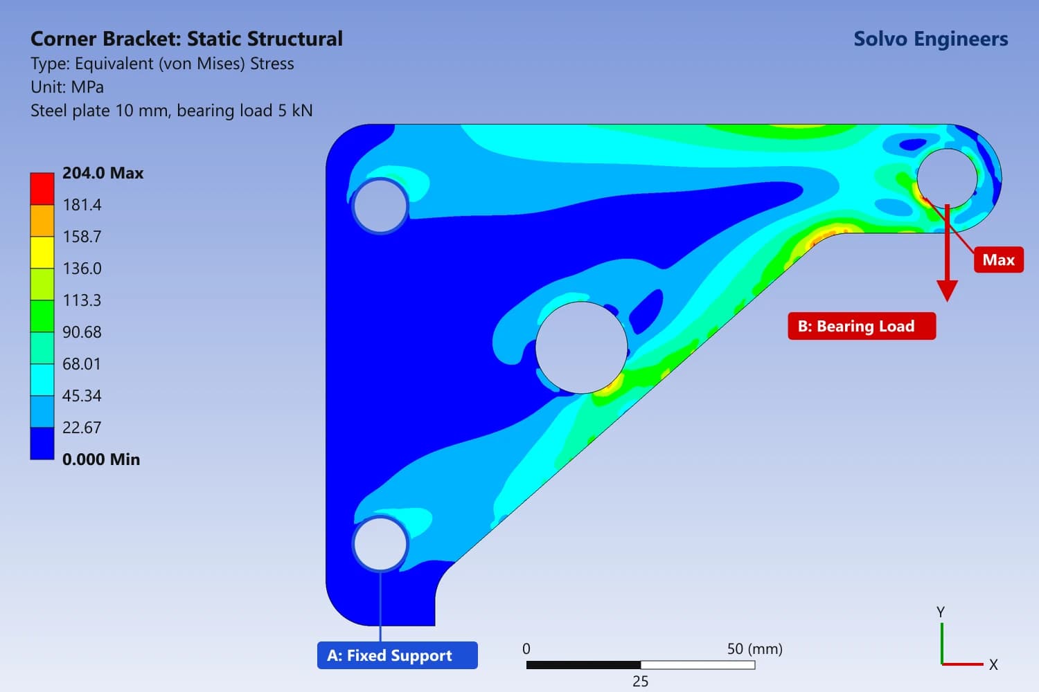
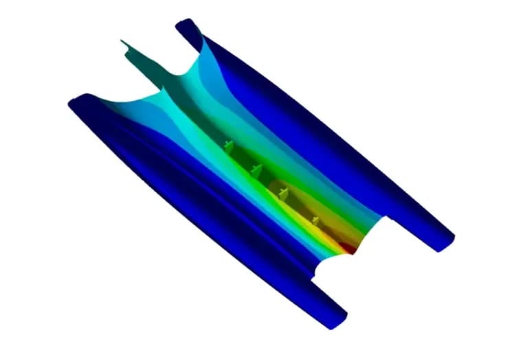
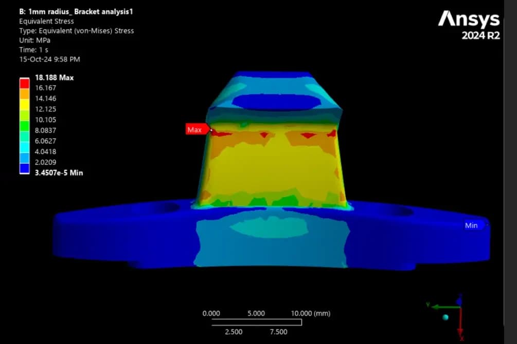
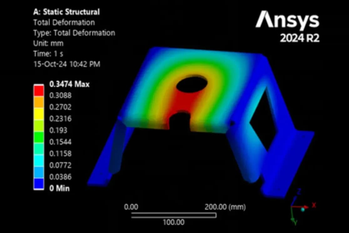
The total deformation plot at the top of this page shows how the bracket moves under load:
The stress and displacement trends confirm a sound design:
Conclusion and next steps
The analysis confirms that the bracket can withstand typical static loads without excessive deformation. With a maximum displacement of 0.347 mm it shows excellent stiffness and load resistance, so it suits structural and mechanical systems where dimensional stability is critical.
The model is also a basis for further optimisation, such as weight reduction or a change of material, especially for mass-produced or lightweight applications. We walk through this kind of analysis step by step in our guide to static structural analysis in Ansys Workbench.
Frequently asked questions
How much does the beam bracket deform under load?
The maximum total deformation was 0.3474 mm, concentrated around the top central opening and the fillets next to it, with zero movement at the fixed base. That is well within acceptable limits for static loading.
Where is the bracket most highly loaded?
Around the top central opening and its adjacent fillets, which carry higher bending moments and redirect the flow of stress. Even there, the stress changed smoothly, with no singularities or severe concentrations.
What material and boundary conditions were used?
Mild steel as a linear isotropic material with E = 210 GPa, a vertical downward force on the top face, and fully fixed supports at the base mounting holes, on a tetrahedral mesh refined around the critical features.
Could the bracket be made lighter?
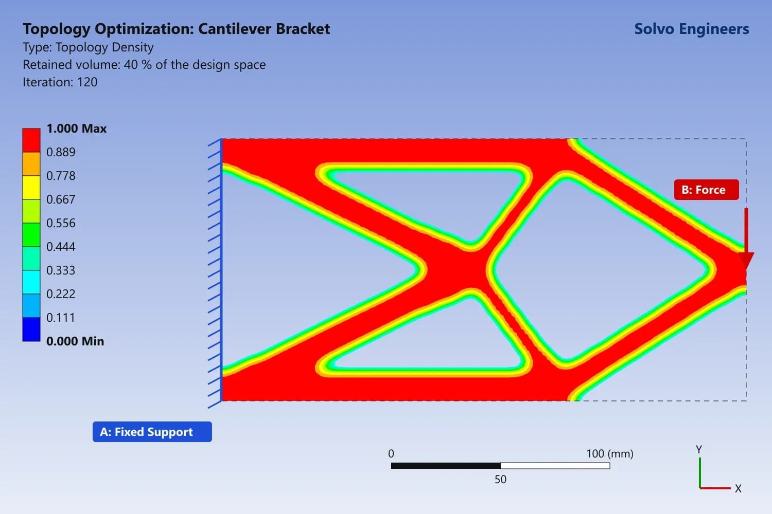
The results give a basis for optimisation such as weight reduction or a change of material, which is most valuable for mass-produced or lightweight applications.