
Fixture and Jig Design with FEA: Stiffness, Clamping and Vibration for Accurate Machining

Introduction
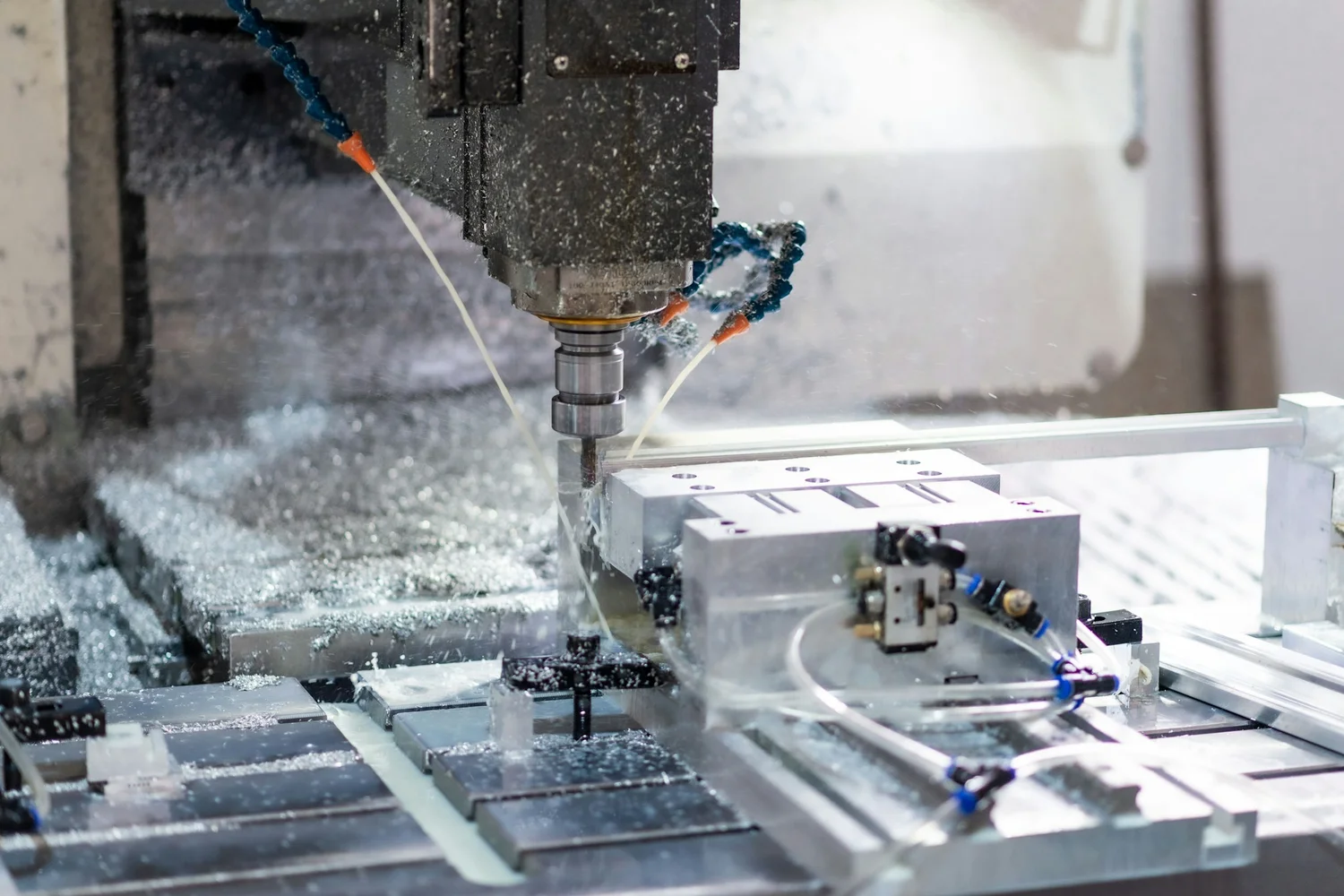
A part can only be as accurate as the fixture that holds it. If the fixture bends under cutting forces, distorts a thin part when it is clamped or vibrates at the wrong frequency, the result is scrap, rework and lost machine time, however good the machine is.
Finite Element Analysis (FEA) shows how a fixture and the part in it behave under clamping and cutting loads before the fixture is made. This guide covers what makes a good fixture, what FEA checks, and how to make fixtures stiffer and lighter at the same time.
What Makes a Good Fixture
- It locates the part in exactly the same place every time.
- It clamps firmly without distorting the part.
- It stays rigid against cutting, drilling and clamping forces.
- It does not vibrate at the frequencies the cutting excites.
- It loads quickly, clears chips and is light enough to handle.
The 3-2-1 Locating Principle
A rigid part has six ways to move: three translations and three rotations. The 3-2-1 principle removes all six with the minimum number of locators: three points on the primary datum face, two on the secondary and one on the tertiary. Clamps then push the part against the locators, ideally directly opposite them, so clamping force does not bend the part.
What FEA Checks
- Fixture deflection at the locators under cutting and clamping forces, compared with the part tolerance. It should use only a small share of the tolerance budget.
- Part distortion from clamping: a thin part clamped out of shape is machined flat and springs back out of tolerance once released.
- Stress in fixture plates, locators, clamps and bolts.
- Contact pressure at locators and clamp pads, which can mark soft or finished surfaces.
- Natural frequencies, which should stay away from the tooth-passing frequency of the cutter (spindle speed times the number of teeth).
Clamping Distortion in Thin Parts
Thin walls, castings and large plates are especially sensitive. FEA models the clamping sequence as separate load steps, with contact between the part, locators and clamps, and shows how much the part moves when clamped and how much springs back afterwards. Moving a clamp, spreading the force over a larger pad or adding a support under a thin wall is often enough to bring a part back into tolerance.
Vibration and Chatter
A fixture that resonates near the cutting frequency amplifies vibration, leaving chatter marks, poor finish and short tool life. Modal analysis finds the natural frequencies and mode shapes of the fixture with the part in it, so stiffening can go exactly where the fixture moves most. Our guide to vibration analysis for industrial machinery explains modal analysis in more detail.
Project Examples
In our FEA of an industrial fixture in SolidWorks Simulation, the maximum stress was 146.8 MPa, well below the yield strength of the steel (typically above 250 MPa), and the deflection was minimal. That margin also showed room to remove material and make the fixture lighter.
Fixtures and tooling often work alongside automation. In our structural analysis of a 6-DOF robotic drilling arm, the whole arm and its bolted joints were checked under a 200 N·m drilling torque, the same kind of process load a fixture has to react.
Making Fixtures Lighter
- Material: aluminium weighs about a third as much as steel but is also about a third as stiff, so it needs deeper sections to match.
- Pockets and ribs: FEA shows which material carries load and which can go. Our guide to topology optimization and design for manufacturing explains how to find the best shape.
- 3D printed fixtures suit light-duty work, nests and inspection, once their stiffness has been checked.
- Welded bases need a fatigue check at the welds, covered in our guide to weld fatigue analysis.
What We Need to Start
- 3D CAD of the fixture and the part, or drawings for our 3D CAD team to model.
- The machining operations: tools, speeds and feeds, or the cutting forces if you know them.
- Clamp types, clamping forces and the clamping sequence.
- Part tolerances and materials.
Frequently Asked Questions
How stiff does a fixture need to be?
Stiff enough that its deflection under cutting and clamping loads uses only a small share of the part tolerance. FEA gives the actual deflection so you can compare.
Can FEA predict chatter?
FEA gives the natural frequencies and mode shapes of the fixture and part, which show whether chatter is likely and where to stiffen. Full stability predictions also need the cutting dynamics of the tool.
Steel or aluminium for a fixture?
Steel for maximum stiffness in a compact size, aluminium for lighter fixtures that are handled often. FEA shows whether an aluminium design is stiff enough.
Can you check a 3D printed fixture?
Yes, using properties for the printed material and build direction, so you know it will hold the part accurately.
How do we get a quote?
Send your CAD files and machining details through our contact page. We will reply with a scope, timeline and quote.
Hold Tolerance From the First Part
Our engineers can check your fixture for deflection, clamping distortion and vibration, and show you where it can be made lighter, before it is built. Send us your CAD files and machining details, and we will reply with a clear scope and quote.