Wind Turbine CFD and FEA: Blade Aerodynamics, Power Output and Structural Design

Introduction
A wind turbine has two jobs: turn as much of the wind's energy as possible into electricity, and survive 20 years or more of gusts, storms and millions of load cycles. Get the first wrong and you lose output every day; get the second wrong and you lose a blade, a gearbox or a tower.
Computational Fluid Dynamics (CFD) and Finite Element Analysis (FEA) let turbine developers test both before anything is built. This guide explains how a turbine's aerodynamics, power output and structure are simulated, for small turbines as well as large ones, and what each analysis tells you.
How Much Power Can a Wind Turbine Make?
- Wind speed matters most: the power in the wind grows with the cube of wind speed, so doubling the wind speed gives eight times the power. The site wind and the cut-in speed make a huge difference to annual output.
- The Betz limit: no rotor can extract more than 16/27, about 59 %, of the power in the wind passing through it. The best modern rotors reach around 45 to 50 %.
- Tip speed ratio: the blade tip speed divided by the wind speed. Every rotor has an optimum tip speed ratio where its power coefficient peaks, often around 6 to 8 for three-bladed turbines.
That is why the rotor design, not just its size, decides how much energy a turbine delivers.
CFD of the Rotor and the Power Curve
CFD places the rotor in a rotating region inside a virtual wind field. A steady moving reference frame gives quick performance estimates, and a transient sliding mesh captures unsteady effects such as each blade passing the tower. The results include:
- Torque, rotor speed and power at each wind speed.
- Pressure and velocity around the blades, showing where the flow separates or stalls.
- The wake behind the rotor and the losses at the tips and hub.
Our CFD analysis of a wind turbine in Simcenter STAR-CCM+ predicted rotor RPM, torque and output power at a 15 mph design wind speed, then repeated it at 20 and 25 mph to show how performance climbs with wind speed. Running a full range of wind speeds gives the power curve and the cut-in speed, and combining the curve with the site wind distribution gives an estimate of annual energy production.
Blade Aerodynamics and Airfoils
- Airfoil choice: a high lift-to-drag ratio, gentle stall behaviour and low sensitivity to roughness from insects and leading-edge erosion. Small turbines also need airfoils that work well at low Reynolds numbers.
- Twist and chord: the blade twists and tapers along its length so each section meets the air at the right angle.
- The right tool for each step: 2D airfoil CFD gives lift and drag data, blade element momentum (BEM) tools quickly estimate performance and loads, and 3D CFD captures tip vortices, stall and the effect of the hub and nacelle.
Blades are wings, and the same analysis applies at any scale. Our CFD optimisation of RC aircraft wings and our CFD analysis of a multi-rotor drone use the same lift, drag and rotor flow methods.
Blade Structure: Strength, Stiffness and Fatigue
Blades are built from glass or carbon fibre composites, with spar caps and shear webs carrying most of the load. Layered composite FEA checks:
- Tip deflection, so the blade never strikes the tower.
- Strength under extreme loads such as storm gusts and emergency stops.
- Buckling of the thin skin and shear web panels.
- Bonded joints and the root connection, where the blade is bolted to the hub.
- Fatigue over many millions of cycles from turbulence and from gravity, which reverses its pull on the blade every revolution.
The key standards are IEC 61400-1 for design requirements and load cases, IEC 61400-2 for small wind turbines, and IEC 61400-5 for rotor blades.
Towers, Foundations and Resonance
A rotor shakes its tower at the rotation frequency (1P) and at the blade passing frequency (3P for a three-bladed rotor). Most modern towers are designed as "soft-stiff", with the first natural frequency between 1P and 3P across the operating speed range.
- Modal analysis and Campbell diagrams check the tower, nacelle and rotor together, and show which speeds a variable-speed turbine should pass through quickly.
- Welds and flanges: steel towers are welded tube sections joined by bolted flanges, and both need fatigue checks.
- Door openings are a known weak spot for buckling and fatigue.
- Small turbines on guyed masts or rooftops need the same checks, plus the vibration they pass into the building.
Our guides to vibration analysis and weld fatigue explain these checks in more detail.
Generators, Drivetrain and Nacelle
- Drivetrain: FEA of the main shaft, bearings, gearbox housing and cast hub under fatigue loads.
- Generators: electromagnetic FEA gives the torque, induced voltage and losses. For small permanent-magnet generators it also predicts cogging torque, which can stop a rotor starting in light winds.
- Nacelle cooling: CFD of the airflow keeps the generator, power converter and gearbox oil within their temperature limits.
Our electromagnetic FEA of a wound-field synchronous machine calculated flux, induced voltage and torque for the type of electrically excited machine also used as the generator in some direct-drive wind turbines.
Siting, Wakes and Small Wind
- Wakes: a turbine behind another sees slower, more turbulent wind, so turbines are spaced several rotor diameters apart, more in the prevailing wind direction.
- Terrain and buildings: CFD of the site shows how hills, trees and buildings speed up or disturb the wind. Rooftop turbines in particular need to sit above the turbulent layer around the building.
- Vertical-axis turbines cope with changing wind direction but have lower efficiency and strongly cyclic loads, which transient CFD and fatigue analysis capture.
For simulation across the rest of the energy sector, see our guide to CFD and FEA in the energy industry.
What We Need to Start
- 3D CAD of the rotor, nacelle or tower, or the blade definition (airfoils, chord and twist), or drawings for our 3D CAD team to model.
- Rated power, rotor diameter, operating speed range and how the turbine is controlled.
- Site wind data or the wind class, and the design standard.
- Blade materials and layup, and generator data if relevant.
- What you need to know: power curve, loads, strength, fatigue or resonance.
Frequently Asked Questions
Can CFD predict the power curve of my wind turbine?
Yes. We run the rotor across a range of wind speeds and find the speed at which its aerodynamic torque balances the generator load, which gives the RPM and power at each point. Test data, where you have it, is used to confirm the model.
What is the Betz limit?
The theoretical maximum share of the wind's power a rotor can capture: 16/27, or about 59 %. Real rotors lose some to drag, tip losses and the wake.
Do you work on small and vertical-axis wind turbines?
Yes. Small horizontal-axis and vertical-axis turbines benefit from simulation just as much, especially for low-wind performance, start-up and rooftop siting.
Which standards apply to wind turbine design?
IEC 61400-1 covers the design requirements and load cases for large turbines, and IEC 61400-2 covers small wind turbines with a rotor swept area of up to 200 m².
How do we get a quote?
Send your CAD files, wind data and targets through our contact page. We will reply with a scope, timeline and quote.
Get More Energy from Every Gust
From rotor aerodynamics and power curves to blade strength, tower resonance and generator design, our engineers can test your wind turbine before you build it. Send us your CAD files and wind data, and we will reply with a clear scope and quote.
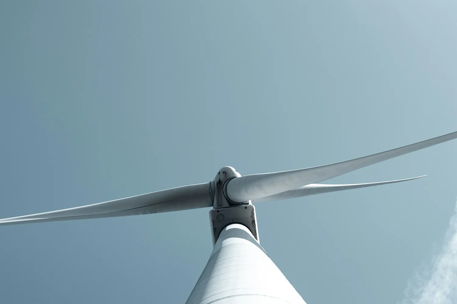
Cover photo: Vadym Alyekseyenko on Unsplash