Heat Exchanger CFD and FEA: Improve Thermal Performance and Prevent Tube Failures

Introduction
Heat exchangers are everywhere in energy and process plants: in power stations, refineries, chemical plants, data centres, HVAC systems and vehicles. When one underperforms, the whole process suffers. Product goes off-spec, energy use rises, and tube leaks or fouling force unplanned shutdowns.
Thermal design software sizes most exchangers well, but it assumes the flow behaves as intended. CFD and FEA show what really happens inside a specific design, from how the flow spreads across the tubes to how the tubesheet copes with thermal expansion. This guide explains where simulation adds the most value and how it fits with standard design methods.
Common Heat Exchanger Problems
- Low duty: the exchanger transfers less heat than its datasheet promises.
- High pressure drop: more pump or fan power, or less flow than the process needs.
- Flow maldistribution: some tubes, channels or plates get too much flow and others too little.
- Fouling and dead zones: slow-moving regions collect deposits that cut performance further.
- Tube vibration and leaks: flow-induced vibration wears tubes at baffles and supports until they leak.
- Cracking from thermal stress at tubesheets, tube-to-tubesheet joints, nozzles and shells, especially in cyclic service.
Where CFD Fits Alongside Thermal Design Software
Thermal design software such as HTRI or Aspen EDR uses proven correlations and is the right tool for sizing standard exchangers. CFD adds the most value where the geometry or the flow is unusual:
- Inlet and outlet headers, nozzles and distributors.
- Non-standard baffles, impingement plates and bypass lanes.
- Compact, finned and plate designs.
- Two-phase flow in condensers and evaporators.
- Troubleshooting an exchanger that is not performing.
Large tube bundles are often modelled as a porous region with resistance and heat transfer from correlations, while headers and nozzles are resolved in full detail. Where detail matters, conjugate heat transfer solves the fluids and the metal together.
Flow Distribution and Pressure Drop
- Shell side: in a baffled shell, part of the flow leaks through baffle clearances or bypasses the bundle instead of crossing the tubes. CFD shows these streams and how much of the flow does useful work.
- Tube side: the header design decides whether every tube gets its share of the flow.
- Plate exchangers: large plate packs can starve the plates furthest from the ports.
- Air-cooled exchangers: hot exhaust air can recirculate into the fan inlets, especially in crosswinds.
Our CFD analysis of a cooling duct shows how internal geometry controls flow distribution and pressure loss, our CFD airflow analysis of a fan heater traces air from inlet to outlet through a heating unit, and our industrial dehydrator case study shows CFD evening out the airflow across all 50 trays.
Thermal Performance and Fouling
- Temperatures and heat transfer: CFD maps the fluid and wall temperatures and the local heat transfer, and finds hot and cold spots.
- Wall temperatures matter as much as the outlet temperatures: they drive fouling, coking and, in flue gas service, acid dew point corrosion.
- Fouling risk: maps of velocity and wall shear stress show the slow-moving areas where deposits build up first.
- Condensers and evaporators: boiling and condensation models predict where the phase change happens and how it affects performance.
Flow-Induced Vibration of Tubes
Flow-induced vibration is one of the most damaging heat exchanger failures: tubes rub against baffle holes and supports and wear through. The main mechanisms are:
- Fluid-elastic instability: the most dangerous. Above a critical crossflow velocity, vibration grows rapidly.
- Vortex shedding and turbulent buffeting from the flow over the tubes.
- Acoustic resonance in gas service, which can be very loud and damage the shell and baffles.
Modal analysis gives the natural frequencies of each tube span, including the added mass of the fluid. CFD gives the real crossflow velocities at the riskiest places, such as below the inlet nozzle and around U-bends. The two are then checked against criteria such as those in the TEMA guidelines. Common fixes include impingement plates, extra supports, changed baffle spacing and anti-vibration bars. Our guide to vibration analysis explains modal analysis in more detail.
Tubesheets, Thermal Stress and Flanges
- Tubesheets: in fixed-tubesheet exchangers, the shell and tubes run at different temperatures and grow by different amounts, which may call for an expansion joint. ASME Section VIII, Division 1, Part UHX covers standard tubesheets, and FEA handles the cases outside it.
- Thermal transients: start-ups, shutdowns and upsets cause thermal fatigue at tube-to-tubesheet joints and nozzles.
- Bolted flanges: bolt preload, pressure and temperature together decide whether the joint stays strong and sealed.
Our FEA of a hairpin heat exchanger bolted flange applied a bolt preload of about 1,350 kN followed by 2.07 MPa of internal pressure, then checked the stresses against ASME limits and the gasket contact pressure for sealing. For the code side, see our guide to pressure vessel FEA to ASME Section VIII Division 2.
Troubleshooting an Existing Exchanger
When an exchanger in service underperforms, vibrates or leaks, we build the model from its drawings and tune it to your operating data: flows, temperatures and pressure drops. The model then shows the cause, whether maldistribution, bypassing, fouling or vibration, and lets you test fixes such as sealing strips, inlet distributors or baffle changes before the next shutdown.
What We Need to Start
- The datasheet: exchanger type, duty, fluids, flows, temperatures, pressures and fouling factors.
- Drawings or 3D CAD, including the tube layout and baffle details, or drawings for our 3D CAD team to model.
- Fluid properties, especially for mixtures or two-phase flow.
- Operating and inspection data: measured performance, leak locations, fouling patterns or vibration.
- Your question: performance, pressure drop, vibration, stress or code compliance.
Frequently Asked Questions
Can CFD replace HTRI or Aspen EDR?
No, and it does not need to. Thermal design software sizes the exchanger; CFD checks the details it cannot see, such as headers, nozzles, bypass streams and unusual geometry.
Can you find out why our exchanger is underperforming?
Yes. With drawings and operating data we can usually pinpoint the cause and show which fix will restore performance.
How do you check tubes for flow-induced vibration?
We combine the natural frequencies of the tube spans from modal analysis with the crossflow velocities from CFD, and compare them with recognised criteria such as the TEMA guidelines.
Do you work on plate, air-cooled and compact exchangers?
Yes, as well as shell-and-tube and hairpin exchangers, HVAC coils, radiators, cold plates and electronics cooling.
How do we get a quote?
Send your datasheet, drawings and the problem you are seeing through our contact page. We will reply with a scope, timeline and quote.
Get Your Heat Exchanger Working as Designed
Whether you are designing a new exchanger or fixing one that underperforms, vibrates or cracks, our engineers can find the cause and show you the fix. Send us your datasheet and drawings, and we will reply with a clear scope and quote.
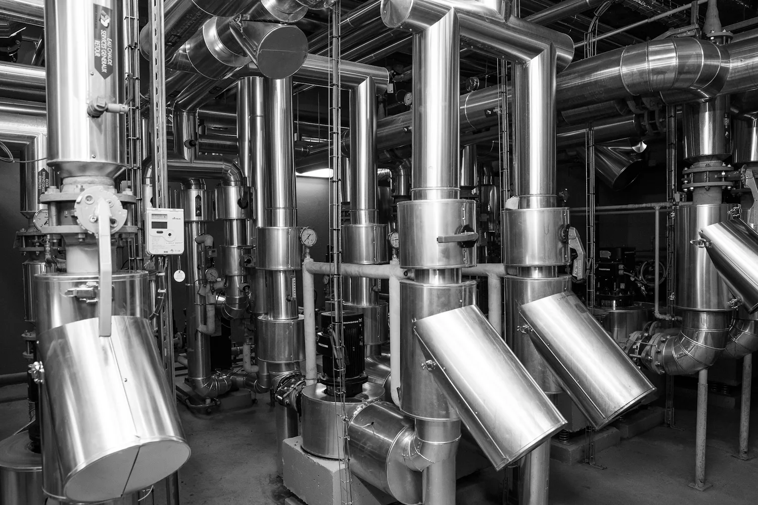
Cover photo: Lionel SEE on Unsplash