Ansys Workbench Static Structural Analysis: A Practical Step-by-Step Guide

Introduction
Static structural analysis is the most common job in Ansys Workbench: working out how much a part deflects and how highly it is stressed under steady loads. The software makes it easy to get a colourful result. Getting a result you can trust takes a few extra steps that many tutorials skip.
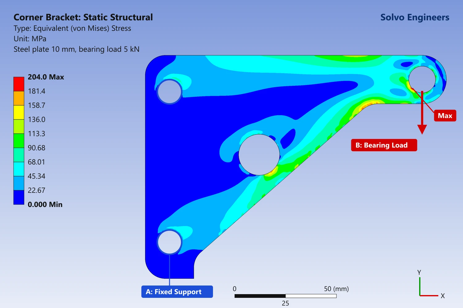
This guide walks through a static structural analysis in Ansys Workbench step by step, from geometry to results, with the checks we use on every project. The cover shows a static structural analysis we ran for this guide: a 10 mm steel corner bracket held at two bolt holes, with a 5 kN bearing load at its tip hole.
What a Static Structural Analysis Answers
It calculates deformation, stress, strain, reaction forces and safety factors for loads that do not change with time, such as weights, pressures, bolt preloads and steady forces. It is not the right tool for:
- Impacts, drops and crashes, which need explicit dynamics.
- Vibration and resonance, which need modal and harmonic analysis.
- Repeated loading, which needs a fatigue assessment on top of the stresses.
Step 1: Set Up the Project
In the Workbench Project Schematic, drag a Static Structural system from the Toolbox. It creates a chain of cells: Engineering Data, Geometry, Model, Setup, Solution and Results. Set the unit system you will work in early (for example millimetres, newtons and seconds) so loads and results are read correctly.
Step 2: Define the Materials
- Engineering Data starts with Structural Steel (Young's modulus 200 GPa, Poisson's ratio 0.3). Change it for anything that is not steel.
- Add materials from the built-in libraries or enter your own, such as a specific aluminium alloy or plastic grade.
- For loads beyond yield, add plasticity data; a linear material will happily report stresses no real metal could reach.
Step 3: Prepare the Geometry
- Import the CAD (STEP, Parasolid or native) and open it in SpaceClaim or DesignModeler.
- Remove details that do not affect the result, such as logos, lettering and tiny features far from critical areas.
- Split faces where loads and supports act, so they are applied to the real contact areas.
- Use symmetry where the part and its loads allow it, and shell elements (a mid-surface) for thin sheet metal.
Step 4: Contacts and Connections
Workbench detects contacts automatically and makes them bonded by default, gluing the parts together. That is right for welded or glued joints, but wrong for parts that can slide or separate:
- Use frictional or no-separation contact where surfaces can move relative to each other.
- Model bolts with pretension, so the joint behaves like the real assembly.
In our FEA of a bolted flange joint, the bolts were preloaded to about 1,350 kN in a first load step before 2.07 MPa of internal pressure was applied, so the contact pressure on the gasket could be checked properly.
Step 5: Mesh and Check It
- Start with the default mesh, then refine it at fillets, holes and anywhere stress changes quickly.
- Check mesh quality metrics such as element quality and skewness.
- Run a mesh convergence check: refine the mesh until the result you care about changes by only a few per cent.
In our FEA of a nylon injection-moulded bracket, the mesh was refined around the fillets, load-bearing supports and mounting hole, where the stresses peak.
Step 6: Apply Supports and Loads
- Supports: a Fixed Support makes a face perfectly rigid, which real mountings rarely are. Frictionless supports, remote displacements or a modelled mating part are often more realistic.
- Loads: forces, pressures, moments, bearing loads, bolt pretension and gravity. Spread loads over real contact areas; a force at a single point creates a meaningless stress peak.
- Large deflection: turn it on in the analysis settings when deflections are large compared with the part, as in thin or flexible parts.
Step 7: Solve and Read the Results
- Total Deformation: how far each point moves. Results are shown exaggerated by default, so switch to true scale to judge the real shape.
- Equivalent (von Mises) Stress: compared with the yield strength for ductile metals.
- Safety Factor: from the Stress Tool, showing at a glance where the design is weak.
- Reaction forces: to confirm the model carries the loads you applied.
On the corner bracket on this page's cover, the stress peaks at about 204 MPa beside the loaded hole, with smaller peaks at the rounded inner corner and around the lightening hole, while the maximum deflection is only 0.18 mm. Against a typical structural steel yield of about 250 MPa, that is a safety factor of about 1.2 at the hottest spot. A peak right where a load is applied always deserves a second look: is it a real bearing stress, or a result of how the load was modelled?
In our FEA of a beam bracket in Ansys 2024 R2, the total deformation peaked at about 0.35 mm around the central opening. In our FEA of a battery module frame, the safety factor plot showed most of the frame was fine, but one small region near the lower mounting area dropped to about 0.41.
Step 8: Check the Results Before You Trust Them
- Compare with a hand calculation, even a rough one; a big difference means something is wrong.
- Check that reaction forces balance the applied loads.
- Check the units of every load and result.
- Ignore stress peaks at sharp re-entrant corners, point loads and fixed edges. These are singularities: the stress rises without limit as the mesh is refined, and does not reflect the real part.
- If stresses exceed yield, a linear analysis is no longer valid, so add plasticity or change the design.
- For contact models, check the contact status and pressure.
Common Mistakes
- Leaving every contact bonded.
- Fixed supports on faces that can actually move or rotate.
- Point loads, and reading the stress right under them.
- Keeping the default material.
- Forgetting gravity, bolt preload or thermal loads.
- Skipping the mesh convergence check.
What We Need to Start
- 3D CAD of the part or assembly, or drawings for our 3D CAD team to model.
- Materials, loads and how the part is supported.
- Your acceptance criteria: allowable stress, deflection or safety factor, or the code you design to.
Frequently Asked Questions
Is Ansys Workbench the same as Ansys Mechanical?
Workbench is the project environment that links the steps together. Ansys Mechanical is the application inside it where you set up the model, mesh, loads and results for structural analyses.
Why is the stress so high at one corner?
Most likely a singularity at a sharp corner, point load or fixed edge. Add the real fillet radius or judge the stress a short distance away, and check whether it converges as the mesh is refined.
Can I use Ansys Student for commercial work?
No. Ansys Student is licensed for learning and academic use only, so commercial projects need a commercial licence or a consultant who has one.
Can you check an analysis our team has already run?
Yes. We review the setup, mesh, contacts and boundary conditions, and confirm whether the results can be trusted.
How do we get a quote?
Send your CAD files, loads and requirements through our contact page. We will reply with a scope, timeline and quote.
Need Ansys Analysis Done Right?
Our engineers run static structural, nonlinear, thermal and dynamic analyses in Ansys every day, and can take on your analysis or review one your team has set up. Send us your CAD files and requirements, and we will reply with a clear scope and quote.