From sketch to 3D model, CAD helps you refine designs, spot issues early and move faster to manufacturing.

Our 3D CAD design engineers turn sketches, ideas, old drawings and physical parts into accurate, fully parametric models and production-ready drawings. We model parts and assemblies, sheet metal, plastic and machined components, with the tolerances, materials and notes your suppliers need to quote and build them.
Because we are also simulation engineers, our CAD models are built to be analysed: clean geometry, sensible features and correct mass properties, ready for FEA and CFD without rework. When a design needs to be stronger, lighter or cooler, we can test it and update the model in one loop instead of passing files between companies.
We follow consistent modelling standards with controlled revisions, check interferences and assembly sequences, and deliver native files together with STEP, IGES, Parasolid, DWG and PDF drawings, with GD&T wherever fit and function depend on it.

Many projects need design and simulation together, and you can keep both with one team.
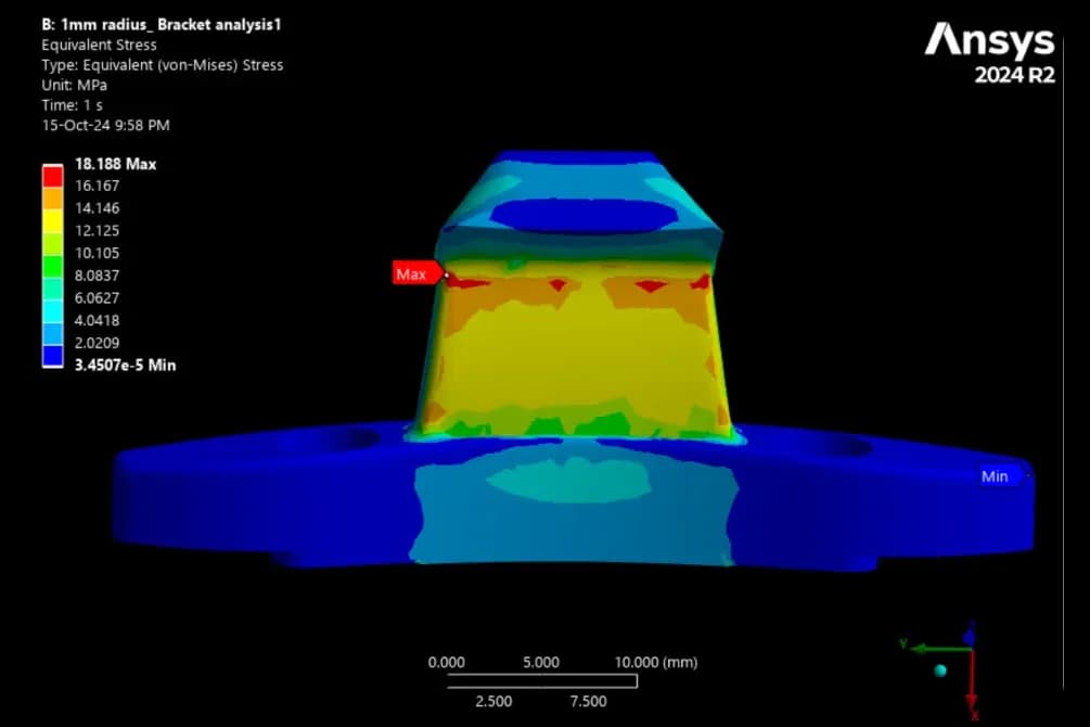
Finite Element Analysis - FEAOur FEA services show how your parts handle stress, vibration and heat, so you can make them stronger, lighter and safer.Explore the service
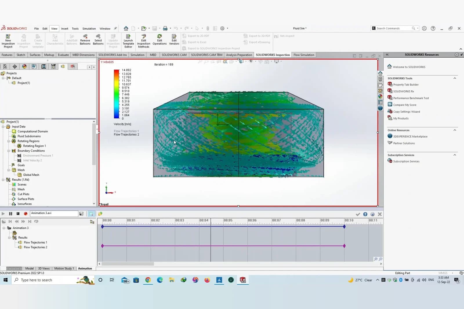
Computational Fluid Dynamics - CFDOur CFD services show how air, water and heat move through your design, so you can make it more efficient and reliable.Explore the serviceWe support a wide range of CAD needs, from concept models to production-ready drawings. Here is what each service covers.

Accurate solid and surface models built from sketches, drawings or specifications, with clean feature trees that are easy to edit.

Multi-part assemblies with proper mates, interference and clearance checks, and exploded views for manufacturing and service.

Flat patterns, bend allowances, reliefs and hardware designed for laser cutting, punching and press brake forming.

Draft, wall thickness, radii, tool access and tolerance reviews so parts can be machined, moulded or cast at a sensible cost.

Driving dimensions and design tables so a family of sizes, or the next revision, comes from one controlled model.

Recreating parts from physical samples, measurements or 3D scans, capturing the datums and tolerances that matter for fit.

Photo-realistic renders and exploded views for pitches, manuals, product pages and design reviews.

2D drawings, PDFs and legacy files rebuilt as native 3D models, or translated cleanly between CAD formats.

Models prepared for 3D printing and CNC prototypes, with tolerances and build orientation chosen for the process.

Datums, feature control frames and tolerances on drawings, so suppliers and inspectors read every feature the same way.

Structured bills of materials linked to the assembly, with part numbers, quantities, materials and purchased components.

Mechanism studies that check range of motion, collisions and joint forces in linkages, hinges and moving assemblies.
A clear, predictable process from your first sketch to files your suppliers can build from.
Sketches, photos, old drawings, a physical sample or an existing model, plus how the part will be made and used.
We confirm the deliverables, file formats and drawing standards, then send a quote for the work involved. Every project is priced individually after we review your inputs.
Parts and assemblies are built parametrically, with the key dimensions and relationships captured so later changes are quick and predictable.
Interference, clearance, mass property and manufacturability checks, plus FEA or CFD when performance needs to be proven.
Manufacturing drawings with dimensions, tolerances, materials and finishes, together with BOMs and exploded views.
Native files plus STEP, IGES, Parasolid, DWG and PDF, with controlled revisions as your design evolves.
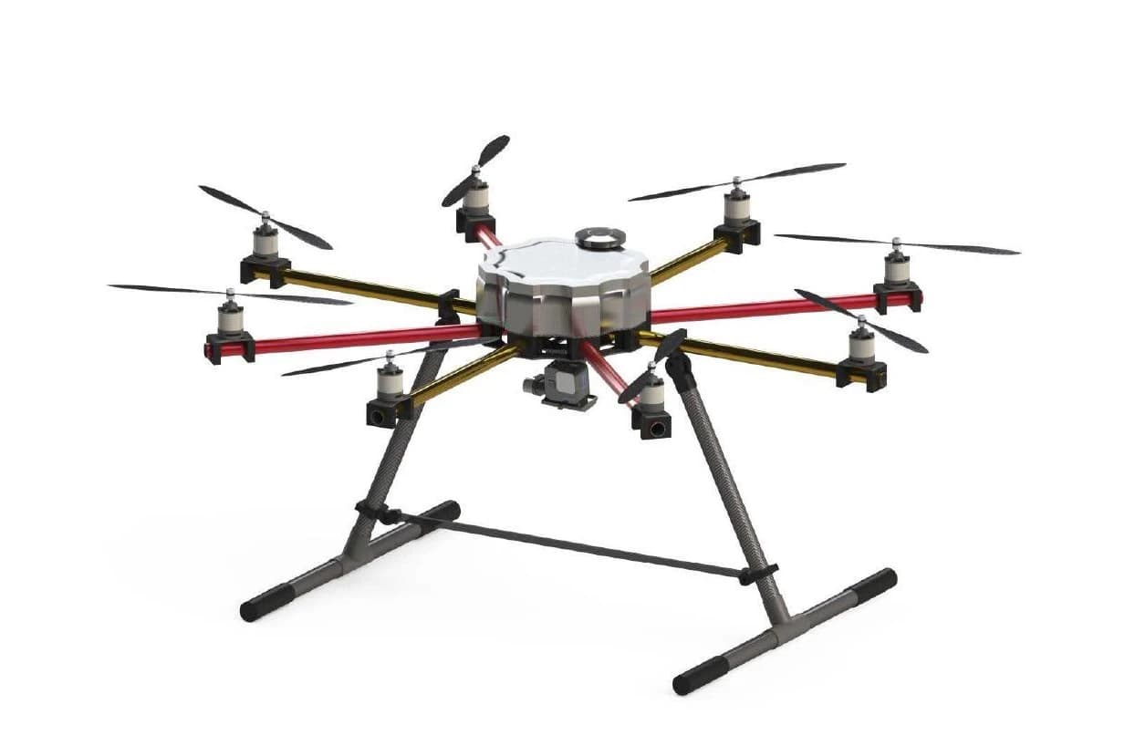
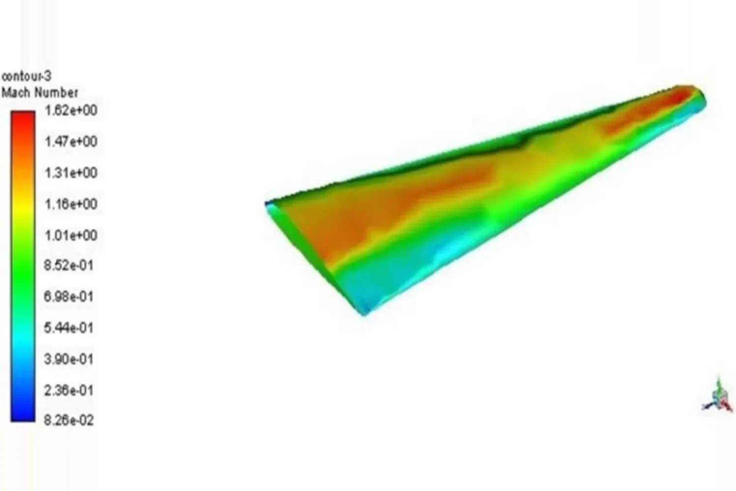
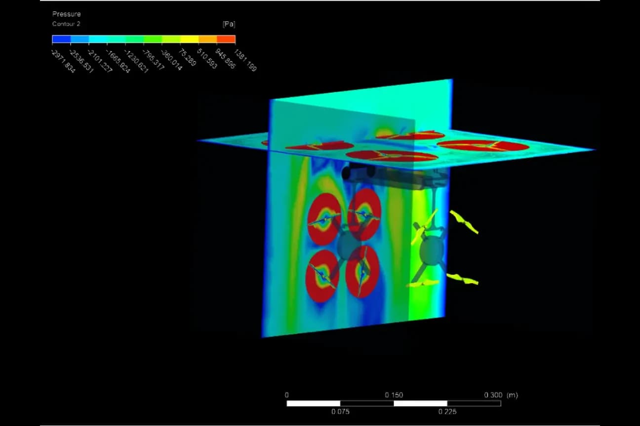
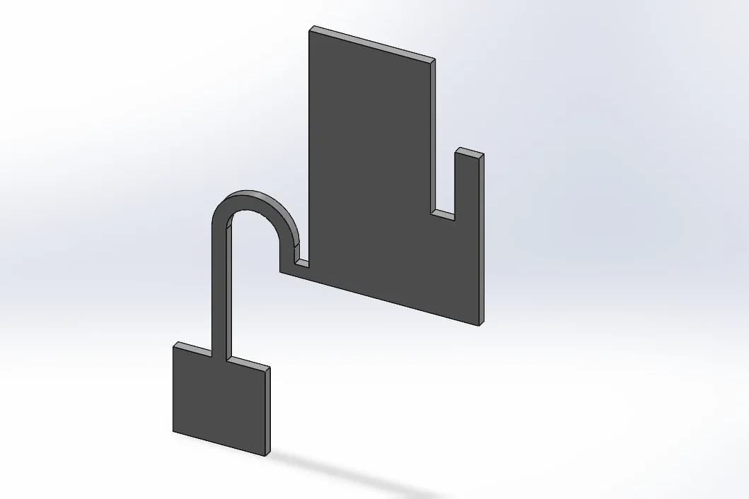
From a production-ready octacopter design with its full bill of materials to the 3D models our team built for simulation projects.
We model in the tools below and deliver in the formats your suppliers use.

Parametric parts, assemblies, sheet metal, weldments and manufacturing drawings.

2D drafting and DWG drawings, plus 3D models for clients who work in Autodesk tools.

Quick concept and layout models for spaces, enclosures and installations.

Cleaning and simplifying CAD for meshing, so models move straight into FEA and CFD.
At SOLVO Engineers, We Commit To Delivering Innovative, Focused And Personalized
CAD or computer aided design uses 3D models to plan shape fit and function. Our CAD modeling shows assemblies early, reduces mistakes, and speeds prototypes, tooling, and manufacturing handoff.
3D CAD lets us explore alternatives quickly, test clearances, and check assembly steps. Designs improve earlier, change costs drop, and you get reliable data for simulation, drawings, machining or molding.
We provide 3D CAD modeling, detailed drafting, assemblies, surface modeling, sheet metal, mechanisms, BOMs, exploded views, renderings, and manufacturing packs. We also prepare DFM reviews and handoff packages for suppliers.
Accuracy comes from good constraints, references, and careful checks. We use model validation, interference detection, and controlled revisions so CAD models and drawings match real parts and assembly intent.
Yes. We create dimensioned manufacturing drawings with GD&T where required. Tolerances, notes, materials, and finishes are specified, aligned with your supplier capabilities for CNC machining, sheet metal, or molding.
Yes. We reverse engineer parts using calipers, scans, to recreate accurate CAD geometry. Critical datums and tolerances are captured, and we produce manufacturable drawings and STEP files for production.
Yes. We optimize wall thickness, ribs, draft, and fillets, balancing strength, weight, cost, and manufacturability. DFM and DFA checks reduce machining time, mold complexity, and assembly steps without sacrificing performance.
Most CAD projects complete within days to a few weeks depending on part complexity, revision rounds, and supplier needs. We set clear milestones and communicate progress with checkpoints and reviews.
Send native CAD or STEP files. We clean geometry, defeature where needed, and ensure contacts and loads reflect reality. Good CAD preparation improves mesh quality and speeds accurate simulation results.
At SOLVO Engineers, We Commit To Delivering Innovative, Focused And Personalized
Practical articles on designing parts that perform well and can actually be made.

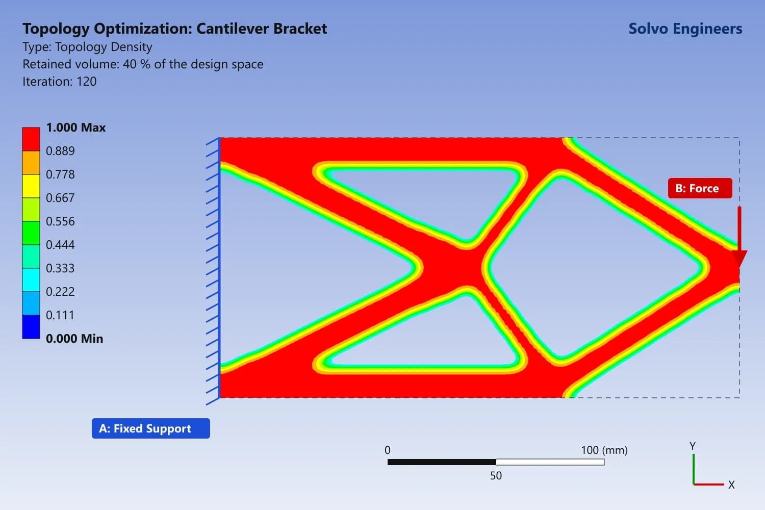
Read the articleHow topology optimization finds the lightest shape for your loads, and how design for manufacturing turns it into a part you can machine, cast or 3D print.

Read the articleDesign injection molded plastic parts that work first time: wall thickness, ribs, bosses, draft, material choice, creep and FEA checks before tooling.

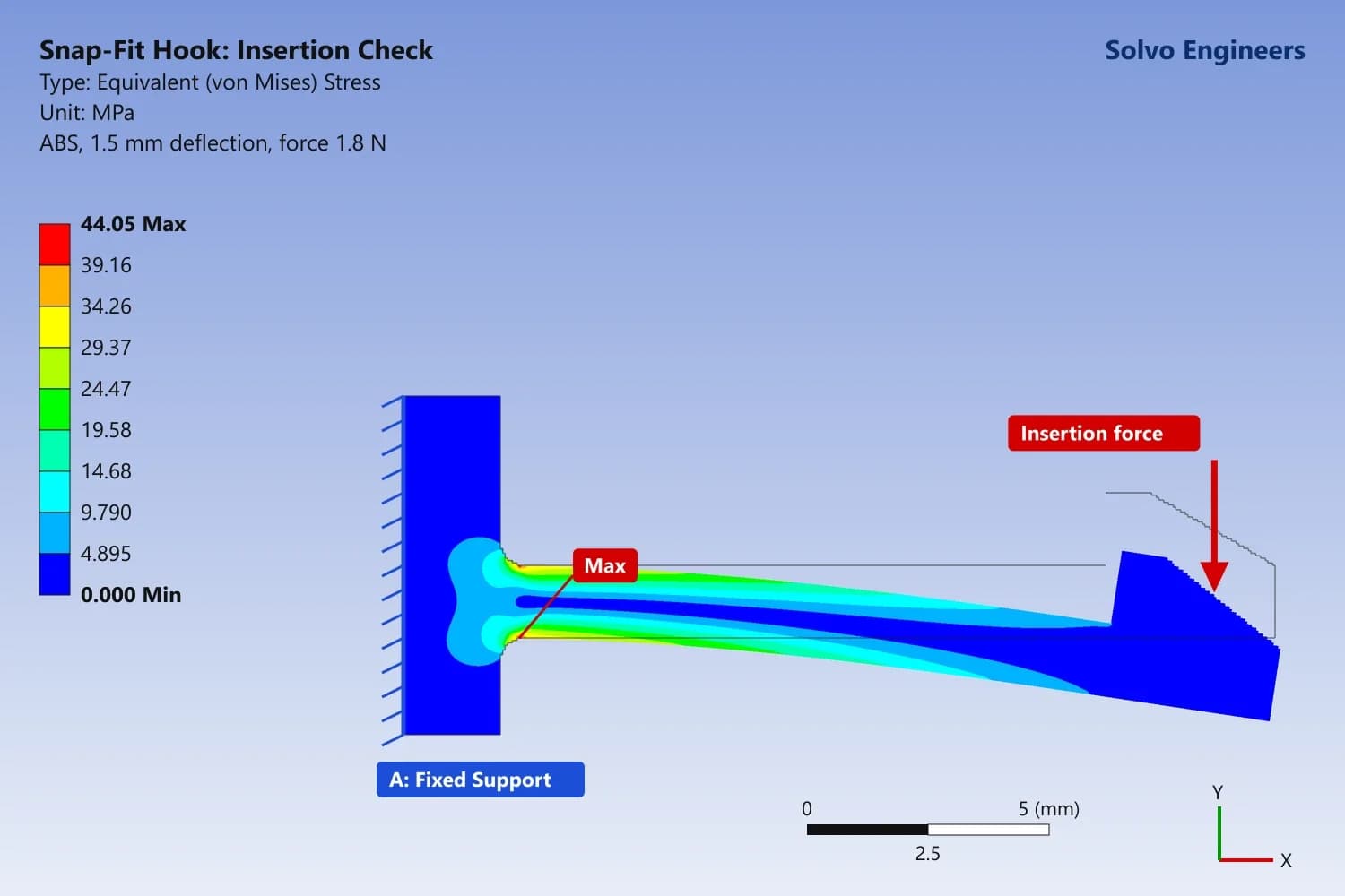
Read the articleA practical guide to cantilever snap-fit design: hook geometry, allowable strain, assembly force and root radius, and how FEA catches cracking before tooling.

Read the articleHow FEA improves machining fixtures and jigs: cutting and clamping forces, deflection, locators, part distortion, vibration, chatter and lighter designs.

Read the articleHow FEA helps robotics teams size robot arm links, joints and end effectors for payload, stiffness and accuracy, and make arms lighter and faster.

Read the articleLearn what FEA and CFD are, how they differ and why simulation helps every industry predict product performance before building physical prototypes.