Project overview
Radio-controlled (RC) aircraft are used for training, recreational flying and UAV work, and a better wing means more stable flight, longer endurance and more lift. Understanding the airflow around the wing is the starting point for any of these gains.
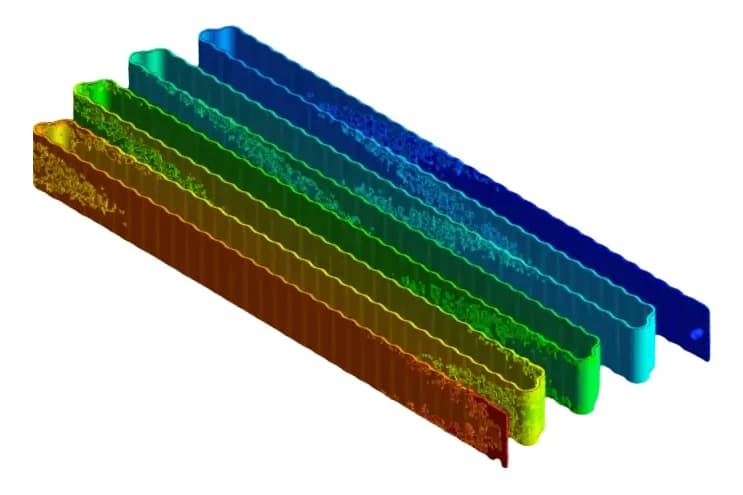
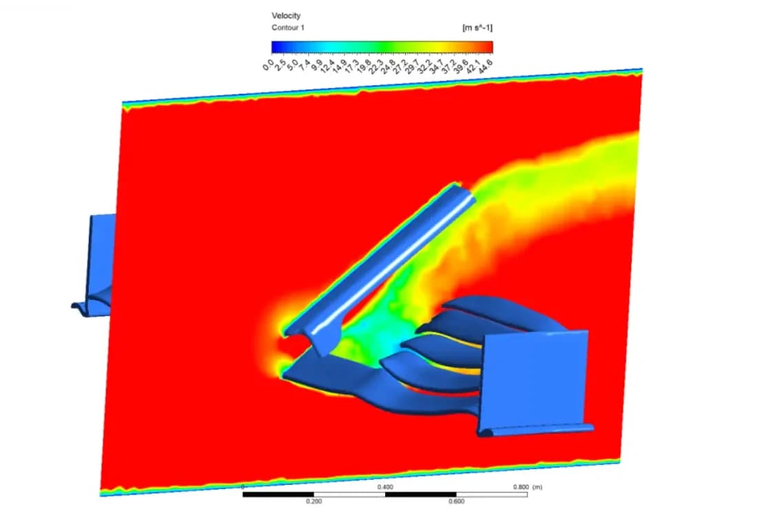
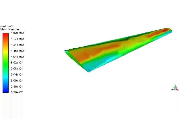
In this project we ran a computational fluid dynamics (CFD) analysis of two custom-designed RC aircraft wings in Ansys Fluent. We compared their lift and drag under identical conditions to find out which configuration, a plain single wing or a multi-winglet design, gives better aerodynamic efficiency for RC flight.
Objectives
The two wing designs
Both wings were modelled in SolidWorks and simulated at the same 13.3° angle of attack, so that the winglets were the only difference:
| Wing | Design | Description |
|---|---|---|
| Wing 1 | Baseline | A plain wing with no winglets, at 13.3° angle of attack |
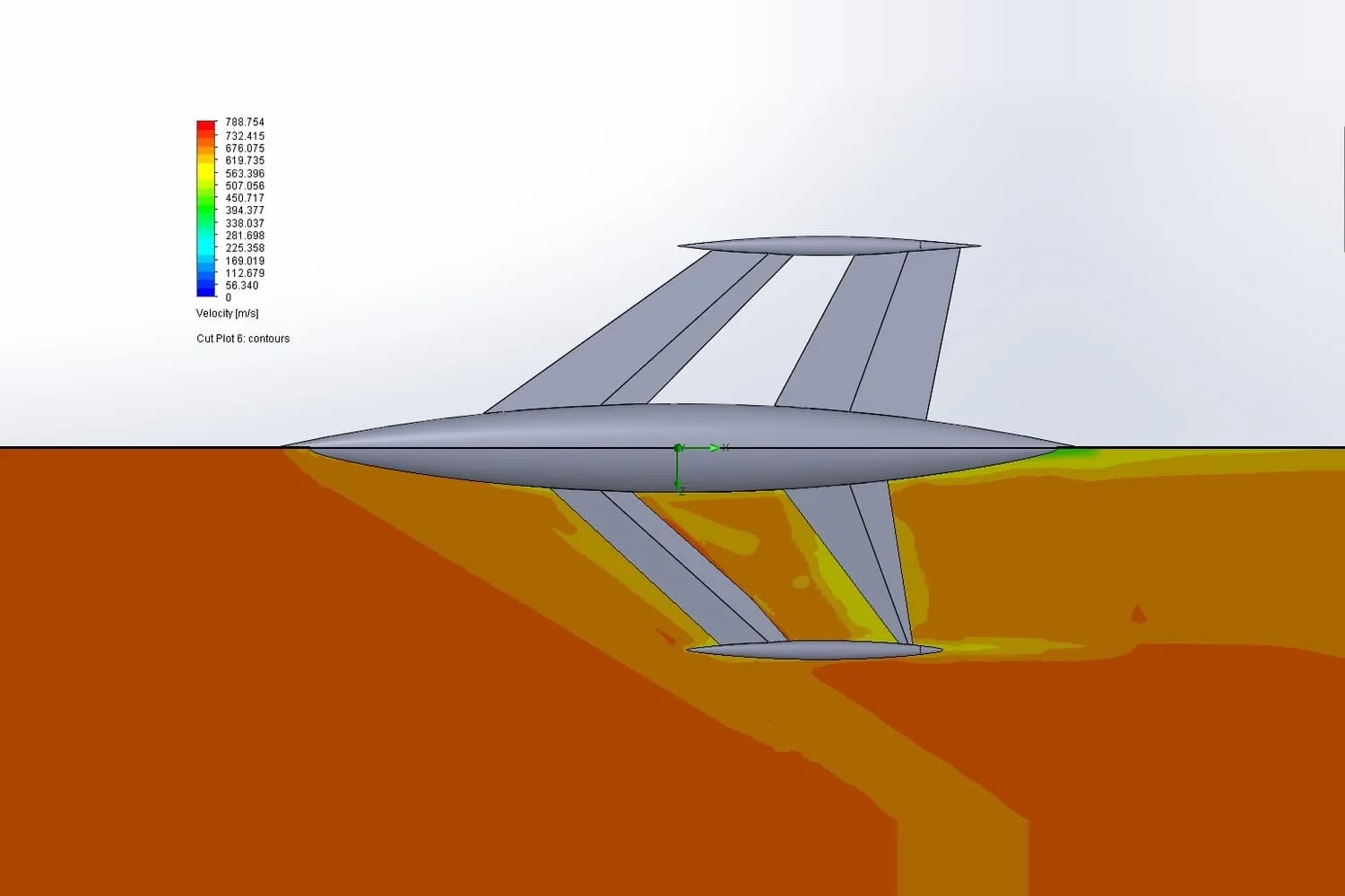
| Wing 2 | Multi-winglet | Three winglet blades at 90°, 0° and −90°, also at 13.3° |
How we set up the wing CFD model
CAD models
Both wings were modelled in SolidWorks and imported for meshing.
Mesh
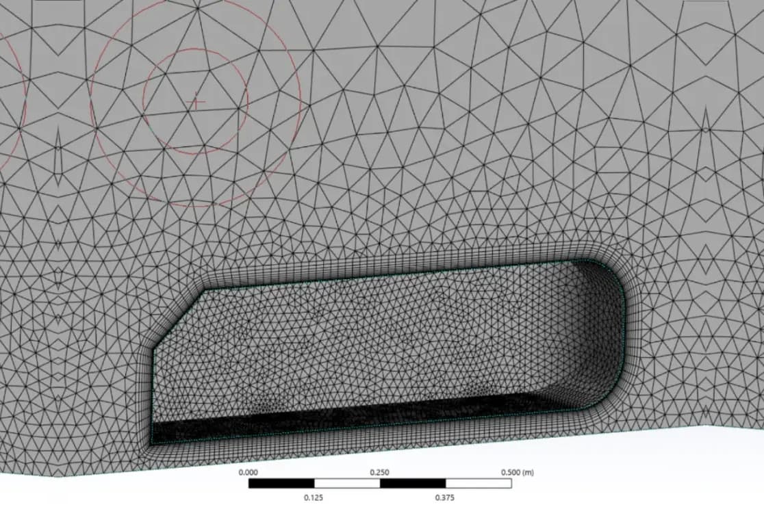
A structured mesh, refined at the wing surfaces and in the wake, where the gradients are steepest.
Solver and turbulence model
Ansys Fluent 21 with the pressure-based solver, steady-state flow and the SST k-ω turbulence model.
Boundary conditions
Pressure far-field boundaries, initialised from the inlet, with 5% turbulence intensity and a viscosity ratio of 10.
Lift and drag
Lift and drag calculated from Fluent's force monitors, using the standard force vectors, and followed until they settled.
| Setting | Value | Notes |
|---|---|---|
| Flow | Steady, turbulent | The same conditions for both wings |
| Solver | Pressure-based | Absolute velocity formulation |
| Turbulence model | SST k-ω | Accurate near the wall and in separated flow |
| Material | Air (ideal gas) | Standard air properties |
| Boundaries | Pressure far-field | Initialised from the inlet |
| Inflow turbulence | 5% intensity | With a viscosity ratio of 10 |
Results: lift, drag and flow behaviour
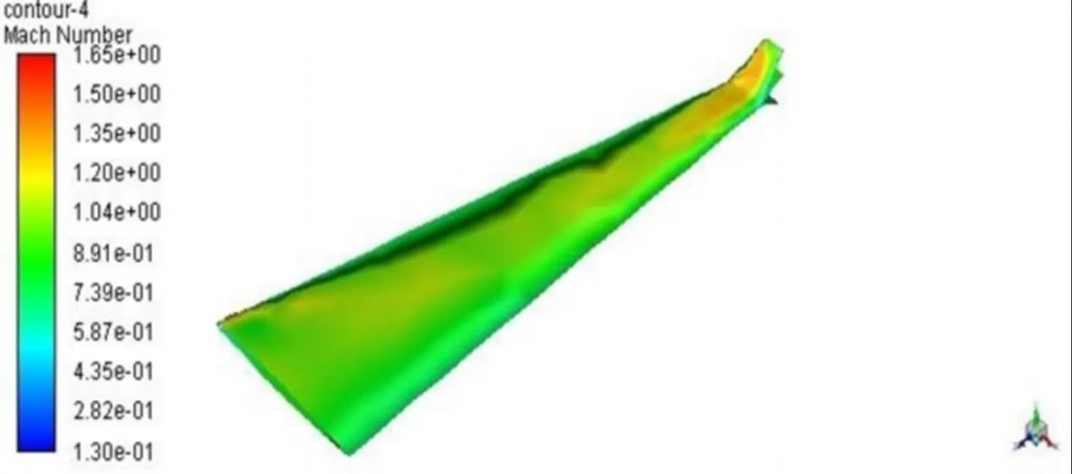
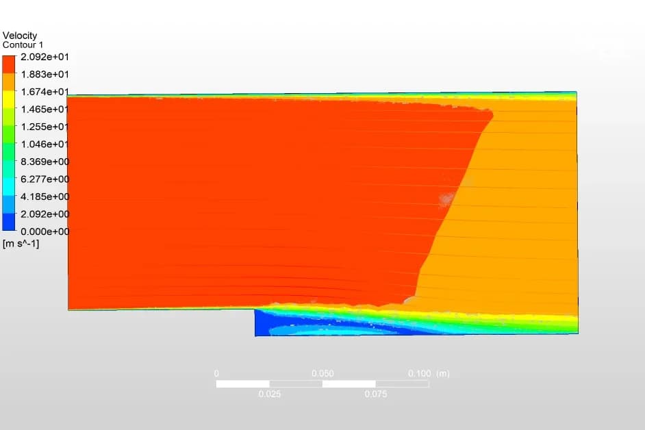
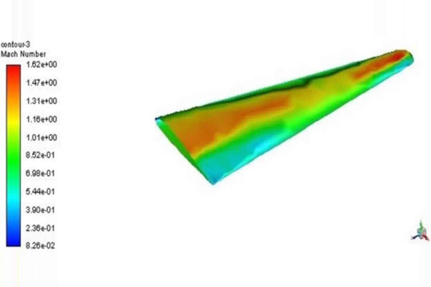
Overall, the multi-winglet wing produced more lift while keeping the drag acceptable. Its winglets helped the flow reattach, delayed separation and improved pressure recovery, making it the more efficient choice for RC flight.
Why CFD matters for small wings
Comparing lift, drag and flow behaviour in simulation showed how directly the wing geometry drives flight performance, before anything was built or flown. The same workflow supports educational and experimental aerospace projects as well as commercial UAV design.
We compared winglet designs on a larger aircraft wing too, in our CFD analysis of aircraft wing and winglet designs.
Frequently asked questions
Do winglets increase the lift of an RC aircraft wing?
In this study, yes. The multi-winglet wing, with three winglet blades at 90°, 0° and −90°, produced significantly more lift than the plain wing at the same 13.3° angle of attack, because of a larger pressure difference between its upper and lower surfaces.
Which wing had the better lift-to-drag ratio?
The multi-winglet wing (Wing 2). Its drag was slightly higher at first before stabilising, but the extra lift gave it a better overall lift-to-drag ratio, along with a narrower wake and better pressure recovery.
What simulation settings were used?
Steady, turbulent flow of air as an ideal gas in Ansys Fluent 21, with the pressure-based solver, the SST k-ω turbulence model, pressure far-field boundaries, 5% turbulence intensity and a viscosity ratio of 10, on a structured mesh refined at the wing surfaces and wake.
Why compare both wings at the same angle of attack?
Keeping the angle of attack (13.3°) and all other conditions the same means any difference in lift, drag or flow behaviour comes from the winglets alone, which makes the comparison fair.