Project overview
Converging-diverging (CD) nozzles are key parts of propulsion systems in aerospace and defence: they convert the pressure and heat of a gas into a fast, directed jet that produces thrust. The flow speeds up through the converging section, reaches the speed of sound at the narrowest point (the throat) and, with a high enough pressure ratio, becomes supersonic in the diverging section.
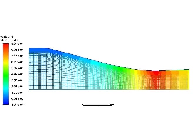
In this project we ran a computational fluid dynamics (CFD) analysis of compressible air flow through a 2D axisymmetric CD nozzle in Ansys Fluent. The aim was to see how subsonic flow accelerates to supersonic speed, follow the static pressure and Mach number along the nozzle, and check the flow regime under choked, expanded conditions.
Objectives
How we set up the nozzle CFD model
2D axisymmetric geometry
The nozzle was modelled as a 2D axisymmetric section: a converging inlet, the throat and a smooth diverging outlet.
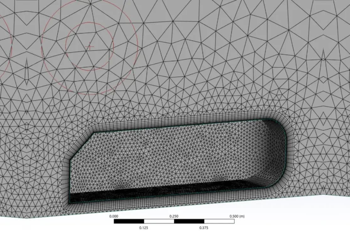
Structured mesh
A high-quality structured mesh, refined near the throat and the outlet to capture the steep pressure gradients and any shocks.
Compressible solver
Fluent's density-based solver for steady, compressible flow, with air modelled as an ideal gas.
Boundary conditions
A total pressure inlet raised high enough to choke the throat, and a static pressure outlet at atmospheric conditions.
Turbulence and walls
The SST k-ω turbulence model, chosen for its accuracy in boundary layers and shocks, with adiabatic, no-slip walls.
Simulation setup
| Setting | Value | Why |
|---|---|---|
| Solver | Density-based, steady | Suited to compressible, high-speed flow |
| Fluid | Air, ideal gas | Density changes with pressure and temperature |
| Inlet | Total pressure | Raised to choke the throat and expand the flow |
| Outlet | Static pressure | Set to atmospheric conditions |
| Turbulence model | SST k-ω | Balances boundary layer and shock accuracy |
| Walls | Adiabatic, no-slip | No heat transfer through the nozzle wall |
Results: Mach number and static pressure
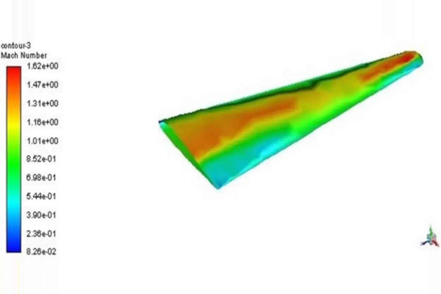
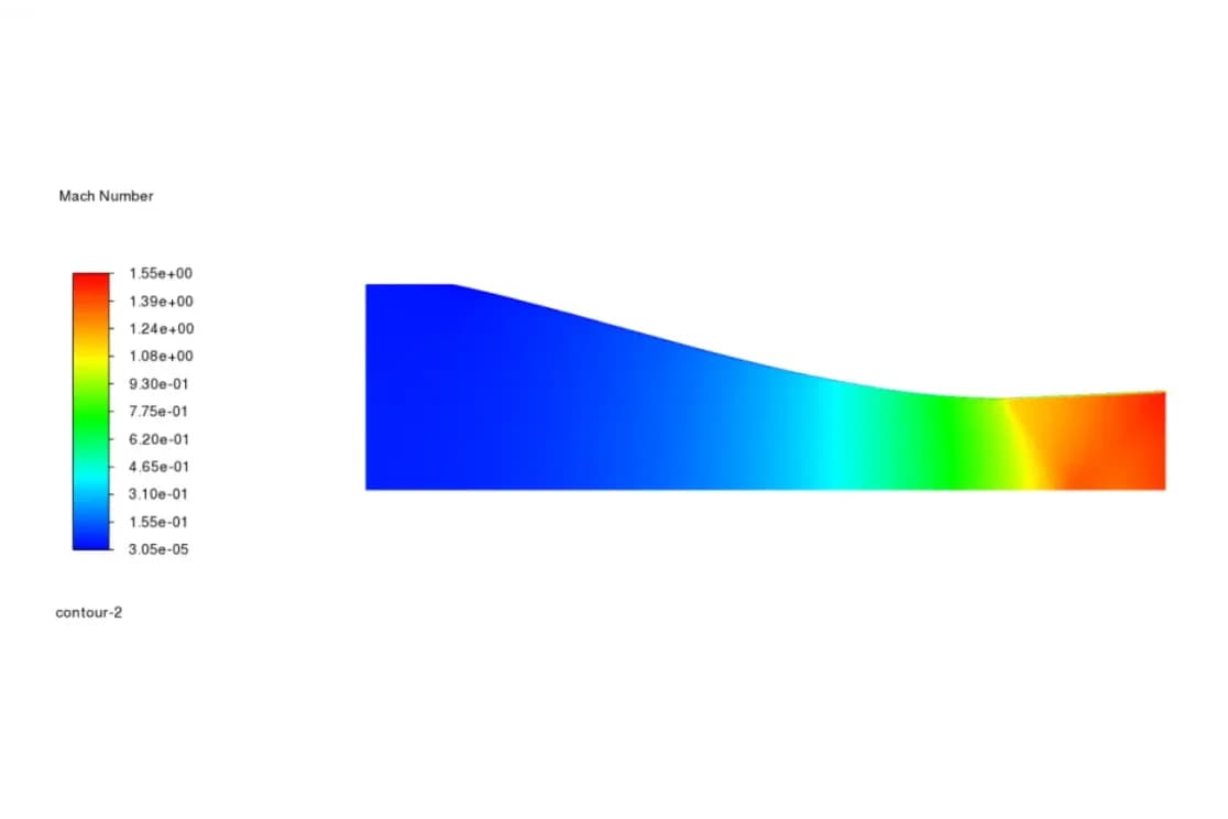
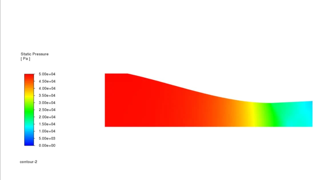
We looked at two results along the nozzle: the Mach number and the static pressure.
Why CFD matters for nozzle design
CFD shows how pressure and velocity change through every part of a nozzle, which helps find the conditions for the best expansion and thrust. Engineers can use simulations like this one to check nozzle designs, improve their performance and cut down on costly physical tests early in development.
Away from its design pressure ratio, the same kind of nozzle forms shocks and expansion waves. We studied those cases in our CFD of a nozzle with choked flow, shocks and expansion waves.
Frequently asked questions
Why does the flow keep accelerating after the throat?
Once the flow reaches Mach 1 at the throat (choked flow), a widening passage makes supersonic flow speed up further, while it would slow subsonic flow down. With a high enough pressure ratio, the diverging section therefore takes the flow beyond Mach 1; in this study it reached Mach 1.55.
Were there any shock waves in the nozzle?
No. At the pressure ratio studied, the Mach number and pressure changed smoothly along the nozzle and closely matched isentropic flow theory, with no adverse pressure gradients or backflow, so the nozzle ran in a well-expanded regime.
Which solver and turbulence model were used?
Ansys Fluent's density-based solver for steady, compressible flow, with air as an ideal gas and the SST k-ω turbulence model. The inlet was a total pressure boundary and the outlet a static pressure boundary at atmospheric conditions, with adiabatic, no-slip walls.
Why use a 2D axisymmetric model for a nozzle?
A round nozzle is the same all the way around its axis, so a 2D axisymmetric model captures its flow with far fewer cells than a full 3D model. That allows a fine, structured mesh near the throat and outlet, where the gradients are steepest.