
Home / Projects / CFD and FEA of a Supersonic Tandem-Wing versus Single-Wing Aircraft
CFD and FEA of a Supersonic Tandem-Wing versus Single-Wing Aircraft
This project asks a design question and answers it from two sides at once. The question is whether a tandem-wing layout, with two wings working together, is a better way to build a supersonic aircraft than a conventional single wing. Answering it properly means looking at both how the air flows over each design and whether the structure can actually survive the loads, so the study pairs CFD for the aerodynamics with FEA for the structure.
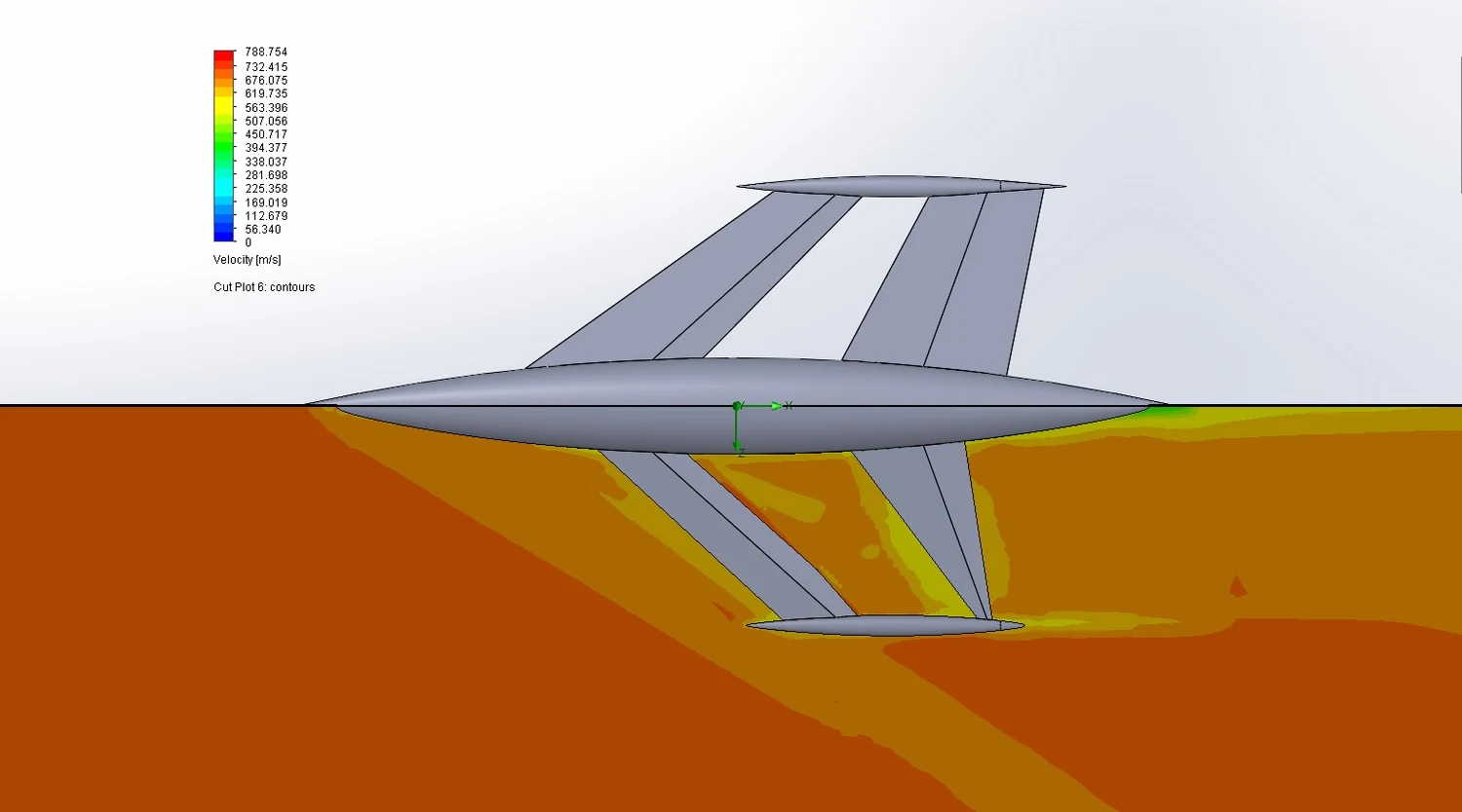
Both aircraft were run through CFD in SolidWorks Flow Simulation at three different angles of attack, capturing the pressure and velocity around each one as the flow pushed into the supersonic range, with speeds in the field reaching up to roughly 788 m/s. The structure was then tested separately with FEA to see what it would take for the wing to hold together under those supersonic loads.
Objectives
The aim was to compare the two wing layouts fairly, on both aerodynamics and structure, across a range of flight attitudes. The objectives were:
- Compare the tandem-wing and single-wing aircraft aerodynamically using CFD, at the same conditions.
- Run each design at three angles of attack, so the comparison holds across different flight attitudes rather than a single point.
- Map the pressure and velocity fields around each aircraft as the flow reaches supersonic speed.
- Check, with FEA, whether the wing structure can survive the loads that supersonic flight puts on it.
CFD Setup
The aerodynamics were solved in SolidWorks Flow Simulation, with the flow domain wrapped around each aircraft and the mesh refined close to the body where the gradients are sharpest. The setup was:
- Tool: SolidWorks Flow Simulation, with air treated as a compressible gas so the supersonic behaviour is captured correctly.
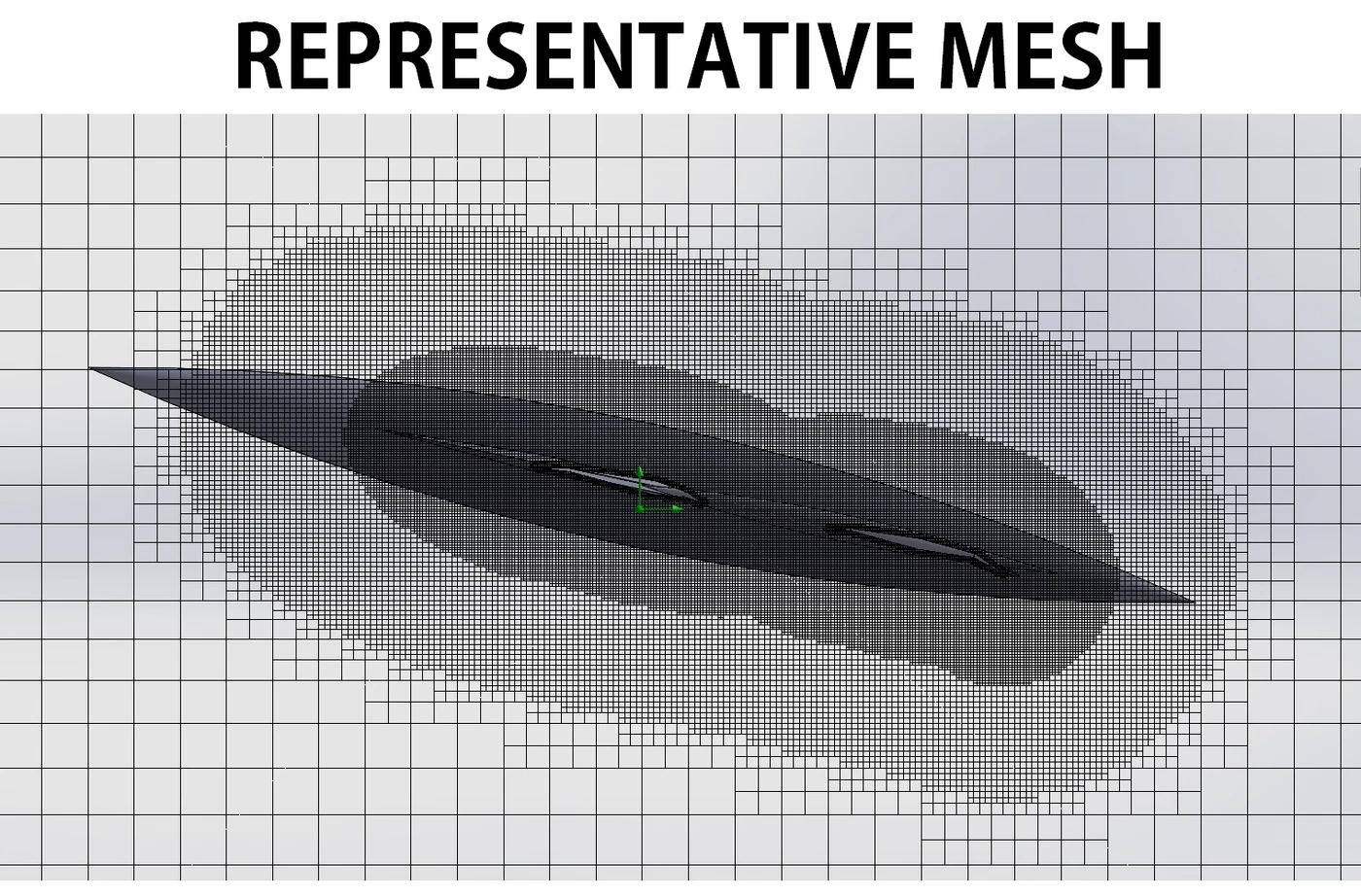
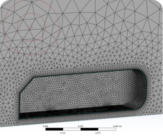
- Mesh: an adaptive mesh that packs finer cells around the aircraft and in the wake, and coarser cells far away, to resolve the flow without wasting cells.
- Conditions: three angles of attack for each design, run into the supersonic range.
- Outputs: surface pressure, pressure cut-planes, and velocity cut-planes, for both the tandem and single-wing aircraft.
Aerodynamic Results
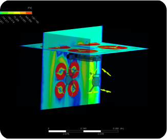
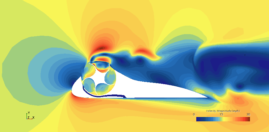

The CFD gives a clear picture of the flow around the tandem-wing aircraft. The velocity field, shown at the top of this page, captures the flow accelerating hard around the body and reaching supersonic speeds, with the sharp changes in the wake that mark compressible, high-speed flow. The single-wing design was run through the same CFD at the same conditions to serve as a baseline, so the tandem results here can be judged like-for-like against a conventional layout.
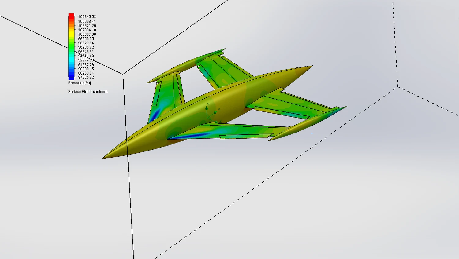
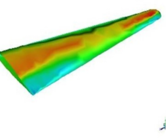
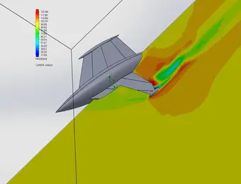
The surface pressure on the aircraft itself shows how the tandem layout splits the aerodynamic load between its two wings. Pressure builds on the forward-facing surfaces and drops over the upper and trailing areas, the pattern that generates lift, and seeing it on both wings at once is what makes the tandem behaviour clear: the load is shared rather than carried by a single surface.
That load sharing is the whole point of a tandem wing, and the pressure plot shows it happening across both wings, which is the behaviour the design is trying to exploit.
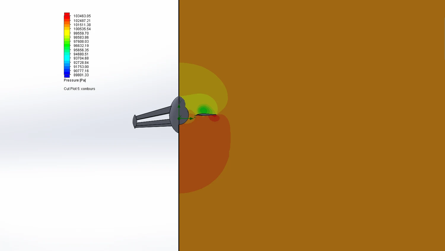
A pressure cut-plane through the flow makes the field around the body easy to read, showing the high-pressure region built up ahead of the aircraft and the lower-pressure zones around it. This is the footprint of a body pushing through the air at speed, and it shows where the flow is being turned and compressed as it passes.
Running this at three angles of attack shows how the loading shifts as the aircraft pitches, which is exactly the information needed to judge one layout against the other rather than guessing from a single case.
Structural FEA and the Stressed-Skin Result
Aerodynamics is only half the problem. A supersonic wing also has to survive the loads it generates, and this is where the FEA produced the most striking result of the whole project. The wing was analysed in two ways, and the difference between them is dramatic.
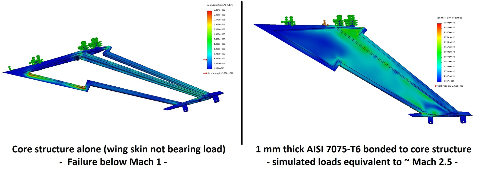
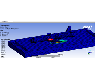
On the left, the internal core structure was made to carry the load on its own, with the wing skin left out of the load path. It fails, and it fails early: the stress runs far past the material yield strength, so this arrangement could not even survive Mach 1. On the right, a 1 mm skin of 7075-T6, a high-strength aluminium alloy, was bonded to that same core so that the skin carries load too. Now the peak stress drops to about 500 MPa, just under the 505 MPa yield strength, and the wing survives loads equivalent to roughly Mach 2.5.
The lesson is a classic one in aircraft structures, shown here in a single clear comparison: the skin is not just a cover, it is structure. By bonding a thin stressed skin to the core, the whole wing shares the load and its strength jumps from failing below Mach 1 to holding together well into the supersonic range. That is the kind of finding that changes a design, and FEA is what makes it visible before anything is built.
Conclusion
Put together, the two halves of the study give a full answer. The CFD shows how the tandem-wing and single-wing aircraft each handle supersonic flow across three angles of attack, providing a fair, like-for-like aerodynamic comparison of the two layouts. The FEA then shows that whichever aerodynamic layout is chosen, the wing structure has to be built as a stressed skin over a core to survive supersonic loads, since the core alone fails below Mach 1 while the skinned structure holds to around Mach 2.5. Aerodynamics and structure have to be judged together, and this project does exactly that.
Aerospace CFD and FEA at Solvo Engineers
High-speed aircraft design is where aerodynamics and structures meet most sharply, and getting either one wrong sinks the design. CFD shows the pressure, the velocity, and the shocks that decide how a wing performs, while FEA shows whether the structure can carry the loads that performance creates. Running the two together, as we did here for a supersonic tandem-wing concept, is what lets a bold design be judged honestly before any metal is cut.
At Solvo Engineers we run aerodynamic CFD and structural FEA in SolidWorks Flow Simulation, Ansys, and SolidWorks Simulation for wings, airframes, UAVs, and high-speed and supersonic designs, covering pressure and velocity fields, lift and drag, stress, and stressed-skin structures. If you are developing an aircraft or any high-speed design and need both its aerodynamics and its structure understood, our team can help. Reach out through our contact page and talk it through with a CAE engineer.
Our Projects
See how Solvo Engineers has helped its clients achieve their vision of digital innovation.

Our Technologies
 Contact Us
Get in touch with us