
Home / Projects / FEA Material Comparison of a Polymer Rod Guard: Polycarbonate vs PA11, PA12 and PA12CF
FEA Material Comparison of a Polymer Rod Guard: Polycarbonate vs PA11, PA12 and PA12CF
Project Summary
Choosing the material for a part looks simple on a datasheet and turns expensive when it is wrong. For this project the client had a rod structure, fixed at its base, whose rods take direct hits from stones, and four candidate polymers on the table: polycarbonate, PA11, PA12, and PA12CF, the carbon fibre filled version of PA12. Rather than argue over datasheet numbers, we ran a static structural finite element analysis (FEA) in Ansys on the same geometry with each material and let the results decide.
A datasheet gives you a material property. It does not tell you how far your part will actually bend when something hits it, because that depends on the geometry as much as the material. By running all four materials through an identical model and load, we could compare them like for like, and by sweeping the load from 8 N up to 12 N we could check whether the ranking held as the impacts got harder. The result was a clear winner and, just as usefully, a clear material to avoid.
Objectives and Approach
The question was straightforward: which of the four polymers keeps the rods stiffest under impact loading, and does that answer stay the same as the load rises? The objectives were:
- Compare total deformation for polycarbonate, PA11, PA12, and PA12CF on identical geometry with identical loading.
- Check the bending stress in each case, so the choice is made on both stiffness and strength rather than stiffness alone.
- Sweep the load from 8 N to 12 N per pipe, so the comparison covers a range of impacts rather than a single data point.
- Give the client a recommendation backed by numbers instead of a datasheet argument.
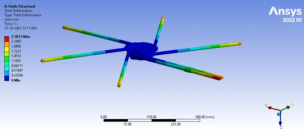
The structure was modelled in Ansys with a fixed support at the bottom, matching how it is mounted, and the force applied directly to the pipes to represent stones striking them. The mesh used a 1 mm element size, giving roughly 478,000 elements and 847,000 nodes, which is fine enough to capture bending along slender rods where a coarse mesh would understate the deflection. Only the material was changed between runs, so any difference in the results comes from the material and nothing else.
Simulation Setup and Loading Conditions
The study was set up as a static structural analysis in Ansys, run once per material and repeated across the load sweep. The main inputs were:
- Materials: polycarbonate, PA11 (polyamide 11), PA12 (polyamide 12), and PA12CF (polyamide 12 with carbon fibre), each with its own stiffness and strength properties.
- Loads: a force applied to each pipe, starting at 8 N and stepped through 9, 10, 11, and 12 N to cover harder impacts.
- Constraints: a fixed support at the bottom of the structure, representing the real mounting.
- Mesh: linear elements at 1 mm size, about 478,000 elements and 847,000 nodes across the model.
- Outputs: total deformation and normal (bending) stress for every material at every load level.
Keeping the geometry, mesh, constraints, and loads identical across all four runs is what makes this a fair comparison. It is the only way to be sure the differences you see are the materials talking, and not the model.
Results and Findings
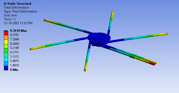
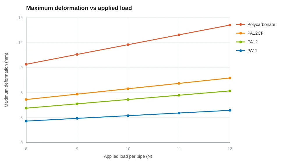
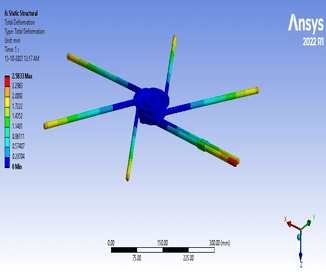
The materials separated clearly, and the gap between best and worst was much wider than a glance at the datasheets would suggest. At the 8 N load, PA11 deflected 2.58 mm, PA12 reached 4.13 mm, PA12CF 5.17 mm, and polycarbonate bent all the way to 9.39 mm. In every case the maximum deflection appeared at the free end of the rods, farthest from the fixed base, which is exactly where a cantilevered rod should move most.
Polycarbonate is the material to avoid here. At 8 N it deflects about 3.6 times further than PA11, and by 12 N it reaches 14.09 mm. For a structure whose rods are meant to stand up to flying stones, that is a lot of movement. A rod that bends that far absorbs the hit by getting out of the way, and risks touching whatever sits behind it.
PA11 came out the winner at every load level. It keeps the rods stiffest, so the structure holds its shape when the stones arrive and takes the shock rather than folding away from it. PA12 was the reasonable middle option, and PA12CF sat between PA12 and polycarbonate in this model.
Sweeping the load from 8 N to 12 N showed something useful: the ranking never changes. Every material deflects in a straight line as the load rises, and the ratio between them stays fixed, with polycarbonate sitting at roughly 3.6 times PA11 at every load. That linearity is worth having, because it means the deflection at any load in this range can be read off without running another simulation, and it confirms nothing is yielding or behaving oddly across the range tested.
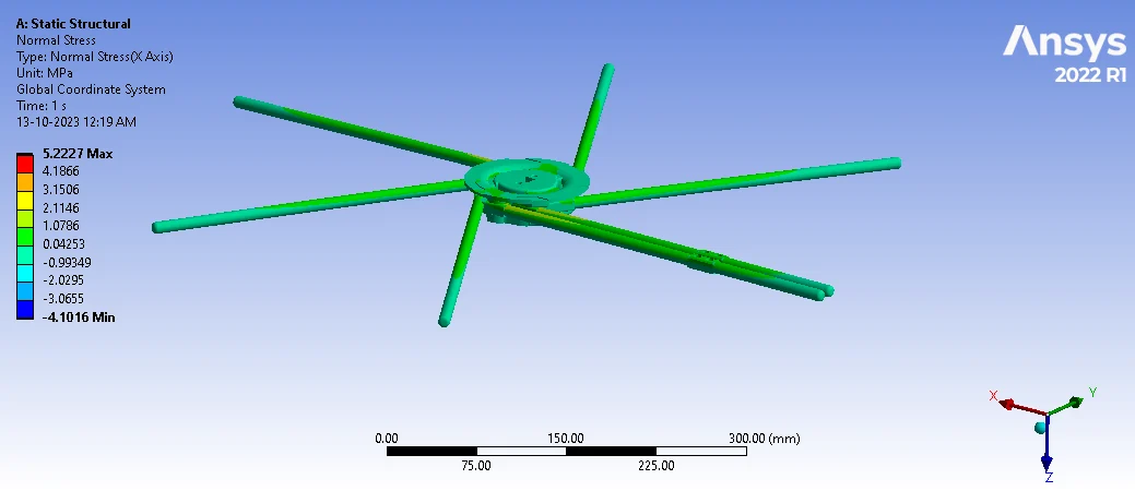
The bending stress result surprises people, so it is worth explaining. The maximum bending stress came out at 5.2272 MPa, and it was the same for all four materials. That is not an error in the model, it is physics. In a statically determinate structure like this one, the internal stress is set by the load and the geometry, not by how stiff the material is. Swap the material and the part bends a different amount, but the stress carrying that load stays the same.
That fact simplifies the decision. Since all four materials see the same modest 5.2272 MPa, and the stress sits low across most of the structure, none of them is anywhere near breaking. Strength is not the deciding factor here. Stiffness is, and on stiffness the materials differ by nearly a factor of four.
The recommendation was PA11, and the reasoning is easy to defend. Every candidate is strong enough, so the choice comes down to which keeps the rods stiffest when stones hit them, and PA11 wins that at every load in the range by a wide margin. Polycarbonate, despite being an obvious first thought, turned out to be the worst of the four for this part. The client got that answer from one model and a handful of runs, instead of building and testing four versions of the same structure.
FEA-Driven Material Selection at Solvo Engineers
Material selection is one of the places where simulation pays for itself fastest, and one of the most often skipped. A datasheet describes a test coupon in a lab, not your part under your loads, and the only fair way to compare candidates is to put them all through the same geometry, the same mesh, and the same load. A study like this takes days rather than the weeks and cost of prototyping in each material, and it replaces an argument with a number. Here the intuitive choice lost, and the data picked a better one before anything was tooled or printed.
At Solvo Engineers we run this kind of comparative structural FEA in Ansys across polymers, composites, and metals, covering deformation, stress, stiffness, and load range studies, alongside our wider FEA and CFD consulting work. If you are weighing up materials for a part, or need to know how a design behaves before you commit to production, our team can help. Reach out through our contact page and talk it through with a CAE engineer.
Our Projects
See how Solvo Engineers has helped its clients achieve their vision of digital innovation.

Our Technologies
 Contact Us
Get in touch with us