
Home / Projects / FEA of a Hairpin Heat Exchanger Bolted Flange Joint for Strength and Sealing
FEA of a Hairpin Heat Exchanger Bolted Flange Joint for Strength and Sealing
Project Summary
A bolted flange is only as good as two things: its strength under load and its ability to stay sealed. For this project we ran a static structural finite element analysis (FEA) in Ansys on the bolted flange joint of a hairpin heat exchanger, where the flange has to clamp tight enough to seal against internal pressure while keeping its stresses within the limits of the ASME pressure vessel code. The parts were modelled with their real ASME materials, the flange in SA-105 forged steel, the pipe in SA-106 Grade B, and the studs in SA-193 Grade B7M.
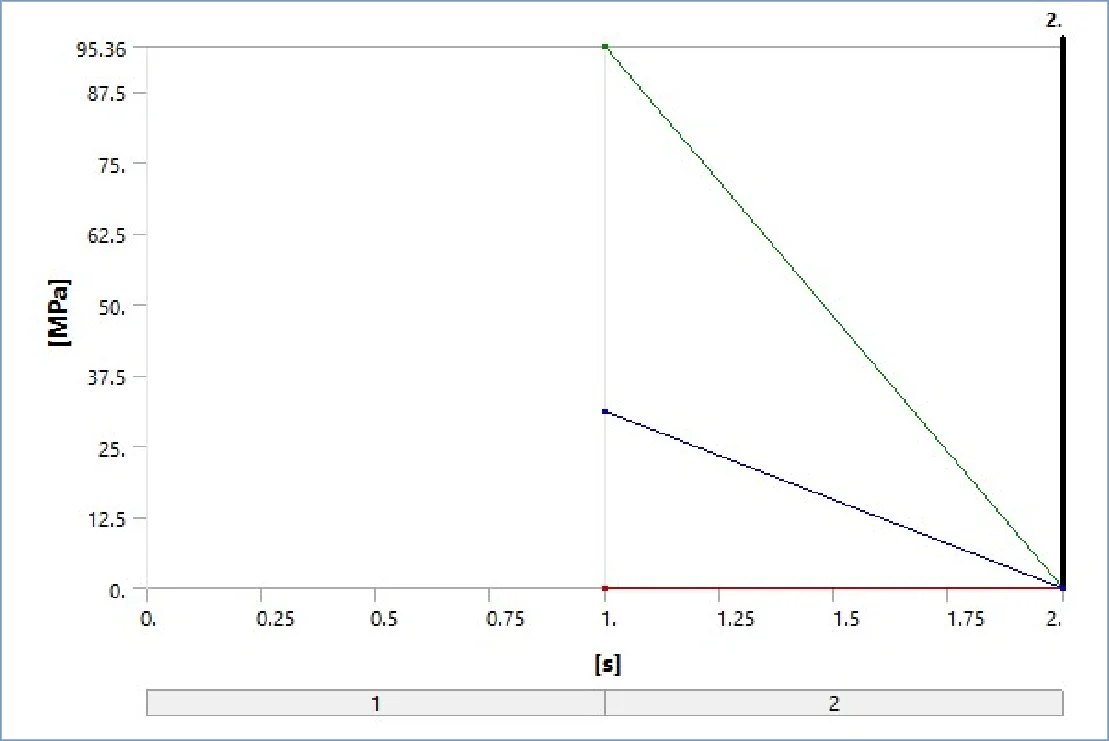
The joint was analysed the way it is actually assembled and used: first the bolts are tightened to a heavy preload of about 1,350 kN, and then, with that preload locked in, an internal pressure of 2.07 MPa is applied to represent operation. That two-stage approach matters, because the bolt-up stresses and the pressurised stresses combine, and it is the combination that decides whether the flange holds and seals. The model gave the client the stress, deformation, and gasket contact data needed to sign the joint off with confidence.
Objectives and Approach
The goal was to prove the flange joint on two fronts at once, its structural strength and its sealing, under the loads it really sees. The objectives for the FEA were:
- Capture the true bolt-up condition by applying the full bolt preload before any pressure, since that preload sets up most of the clamping stress in the joint.
- Add the 2.07 MPa internal pressure on top of the locked preload and find the peak von Mises stress and deformation in the flange, pipe, and bolts.
- Check the contact pressure across the flange faces, because that contact stress is what actually keeps the joint leak-tight.
- Provide linearised stresses so the results can be judged against the ASME pressure vessel code rather than on the raw peak alone.
The full assembly was built in Ansys with contact between the mating parts and the bolts modelled with pretension elements, so the clamp-up and the way the flanges press together were represented properly. Solving it as a two-step load case, bolt-up first and then pressurised operation, let us separate what the preload does from what the pressure adds, which is exactly how a bolted flange is assessed in practice.
Simulation Setup and Loading Conditions
The analysis was set up as a static structural study in Ansys, run in two load steps so the bolt-up and operating stages could be seen on their own and combined. The key inputs were:
- Materials: SA-105 forged carbon steel for the flange, SA-106 Grade B for the pipe, and SA-193 Grade B7M alloy steel for the studs, each with its own strength properties.
- Step 1, bolt-up: a bolt pretension of roughly 1,350 kN applied to the studs to clamp the flanges together.
- Step 2, operation: the preload locked and an internal pressure of 2.07 MPa applied to the wetted surfaces.
- Contact: the flange faces and bolted interfaces set up as contact regions so the parts could separate, slide, or press together the way the real joint does.
- Outputs: total deformation, equivalent von Mises stress, linearised stresses along classification paths, flange contact pressure, and the working load in the bolts.
This setup gives every number an ASME assessment needs from a single model: the peak stresses for a first look, the linearised membrane and bending stresses for the code comparison, the deformation to check flange rotation, and the contact pressure to confirm the joint will seal.
Results and Findings
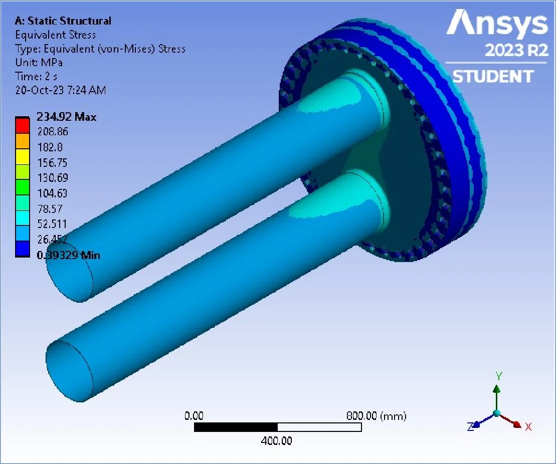
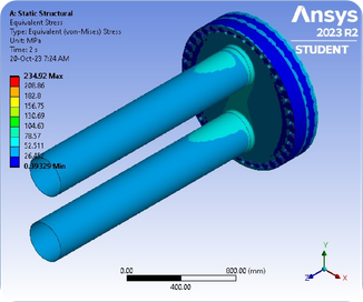
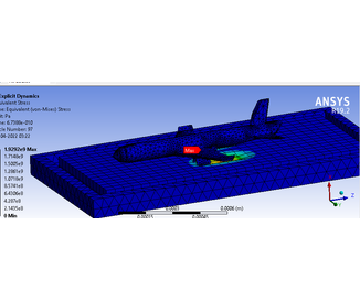
With the preload and the 2.07 MPa pressure both applied, the joint behaved well. The peak equivalent von Mises stress reached about 235 MPa in a small, localised zone at a geometric transition, while the average stress across the parts stayed very low, near 30 MPa. A localised peak like that is expected where the geometry changes sharply, which is exactly why the assessment leans on the linearised membrane and bending stresses rather than the raw peak when it is compared against the ASME allowables.
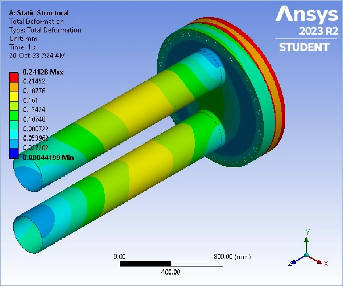
Deformation stayed small. The maximum total deformation was about 0.53 mm once the joint was fully preloaded and pressurised, with most of the assembly moving far less than that. For a flange, keeping the deformation and the associated rotation low is important in its own right, because too much flange rotation is what opens up a gap at the seal and starts a leak.
The low overall stress and the small deflection together show that the flange, the pipe, and the studs all have healthy margin on strength at the rated pressure, so the joint is not being worked anywhere near its limit in normal operation.
Sealing was checked from the contact pressure on the flange faces. The preload keeps a firm, continuous band of contact pressure right around the joint even after the internal pressure tries to push the flanges apart, which is the signature of a joint that will stay leak-tight. Because the analysis tracks this directly, the client could see that the bolt preload was doing its job and did not need to be guessed at from a hand calculation.
Put together, the study answered both questions the client came with. The stresses and linearised results give the evidence of strength for the ASME sign-off, and the contact pressure gives the evidence of sealing, all from one model built the way the joint is really bolted up and run.
Pressure Equipment FEA at Solvo Engineers
Bolted flanges, pressure vessels, heat exchangers, and piping all live or die on the same two questions: is it strong enough, and will it stay sealed? Design-by-rule tables get you part of the way, but once a joint has real geometry, real contact, and combined bolt and pressure loads, a finite element analysis is what shows the true stress state and the true contact pressure. Getting that right on screen is far cheaper than finding a leak or an overstressed flange after the equipment is built and pressurised.
At Solvo Engineers we run this kind of static structural FEA in Ansys for flanges, pressure vessels, heat exchangers, and piping, including bolt preload, contact, gasket sealing, and ASME-style stress linearisation, alongside our wider FEA and CFD consulting work. If you have a bolted joint, a pressure part, or any structural component you need to prove before it is built, our team can help. Reach out through our contact page and talk it through with a CAE engineer.
Related articles
Our Projects
See how Solvo Engineers has helped its clients achieve their vision of digital innovation.

Our Technologies
 Contact Us
Get in touch with us