
Home / Projects / CFD Analysis of a Wind Turbine to Check Output Power and RPM at 15 MPH
CFD Analysis of a Wind Turbine to Check Output Power and RPM at 15 MPH
Project Summary
A client developing a compact wind turbine needed to know, before building a prototype, how much power the design would actually produce and how fast the rotor would spin in real wind. The design point was a 15 mph wind, which is the kind of speed the turbine would see most often at its intended site. We ran a computational fluid dynamics (CFD) analysis in Simcenter STAR-CCM+ to simulate the rotor in a moving airstream, extract its torque and rotational speed, and work out the output power the design can deliver.
Testing a turbine in the field is slow and expensive, and it only tells you the final number, not why the design behaves the way it does. The CFD model shows both. It predicts RPM and power at 15 mph, and because we also ran the same model at 20 and 25 mph, the client could see how performance climbs with wind speed and where the aerodynamic losses sit, all before any metal was cut.
Objectives and Approach
The purpose of the study was to answer the two questions every wind turbine developer asks first: how fast will it spin, and how much power will it make? The objectives we set for the CFD analysis were:
- Predict the rotor's rotational speed (RPM) and torque at the 15 mph design wind speed, and from those compute the output power.
- Repeat the analysis at 20 and 25 mph to see how power and RPM scale as the wind picks up.
- Visualise the pressure and velocity fields around the blades to understand what is driving the rotation and where energy is being lost.
- Map the wake behind the turbine, since the wake shows how much energy has been pulled out of the wind and matters for placement.
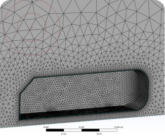
The turbine was modelled in Simcenter STAR-CCM+ with the rotor sitting inside a rotating region, which is the standard CFD approach for spinning machinery. The rotating region hands the flow across an interface to the stationary domain around it, so the blades, the body of the turbine, and the surrounding airstream all interact the way they do in reality. The mesh was refined on the blade surfaces and through the rotor region, where the flow changes fastest, and the wake zone downstream was kept fine enough to hold the wake structure instead of smearing it out.
Simulation Setup and Conditions
Three wind speeds were simulated with the same model so the results could be compared directly. The key elements of the setup were:
- Software: Simcenter STAR-CCM+, solving turbulent airflow around and through the rotor.
- Wind speeds: 15 mph as the primary design case, with 20 mph and 25 mph runs for the performance comparison.
- Rotating region: the rotor enclosed in its own rotating domain, coupled to the stationary outer domain through an interface.
- Monitors: torque on the blades tracked throughout the solution, which is what the RPM and output power numbers are computed from.
- Mesh: fine cells over the blade surfaces and rotor gap, with a refined wake block extending downstream of the turbine.
Convergence was judged on the torque signal settling to a steady behaviour rather than on residuals alone, because torque is the quantity the power prediction depends on. Once each case was converged, the pressure and velocity fields were extracted for the aerodynamic picture, and the torque and rotational speed gave the performance numbers.
Results and Findings
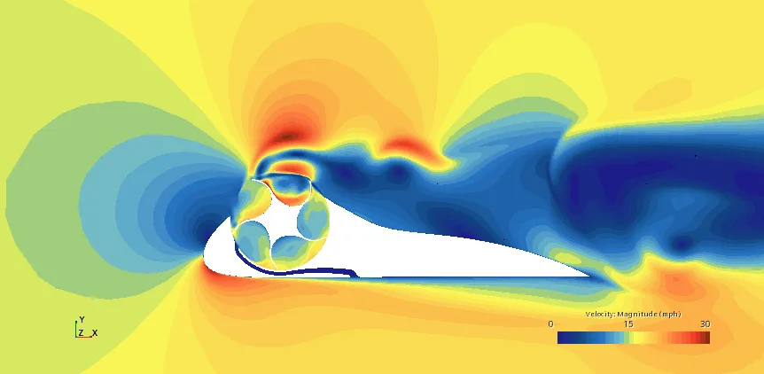
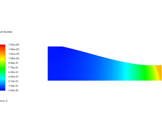
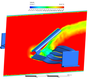
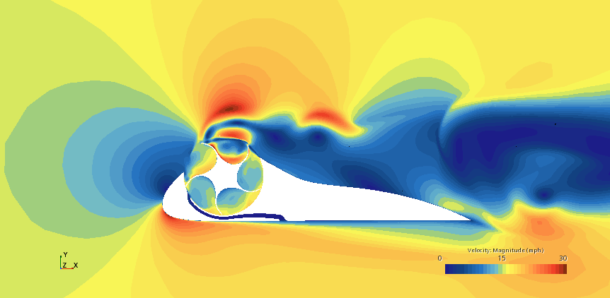
The velocity field at 15 mph, shown above, explains how the design works. The shaped body ahead of the rotor squeezes and accelerates the incoming air, so the flow arriving at the blades is moving noticeably faster than the free wind, with local speeds around the rotor reaching roughly double the incoming 15 mph. That acceleration is exactly what you want, because the energy available to the rotor rises steeply with the speed of the air passing through it. Behind the turbine, a long slow-moving wake shows where the energy has been extracted from the wind.
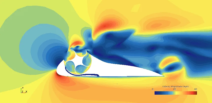
At 20 mph the same pattern holds and simply gets stronger. The accelerated region around the rotor grows, the peak local velocities climb, and the torque on the blades rises with them, which carries straight through to higher RPM and more output power. Comparing the runs showed the expected steep growth of power with wind speed, and confirmed the rotor keeps working cleanly rather than stalling as the wind picks up.
The wake at the higher speed also stretches further downstream. That matters in practice: if several of these units are installed near each other, the spacing needs to respect the wake, or the downstream turbine will sit in slow, disturbed air and lose a large share of its output.
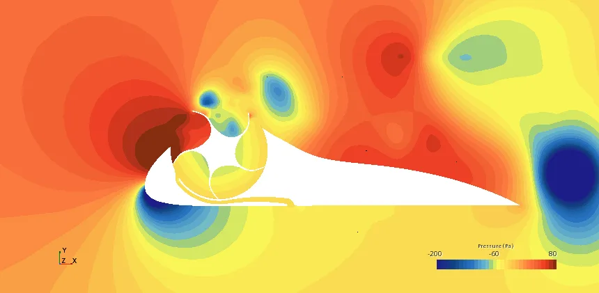
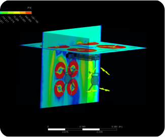
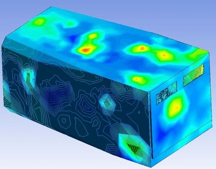
The pressure field at 25 mph completes the picture. A strong high-pressure zone builds on the windward side where the incoming air piles up against the body and the advancing blades, while pockets of low pressure form over the blade surfaces and in the wake. It is this pressure difference across the blades that produces the torque and keeps the rotor turning, and the plot shows it acting exactly where the design intends.
Taken together, the three runs gave the client the numbers they came for, RPM and output power at the 15 mph design point, plus the performance trend up to 25 mph, and just as importantly the aerodynamic evidence behind those numbers. That gives a solid, low-risk basis for sizing the generator, setting expectations for energy production, and moving to a prototype.
Wind Energy CFD at Solvo Engineers
For any wind turbine, the honest performance numbers come from the aerodynamics, and CFD is the fastest way to get them before a prototype exists. A well-built simulation predicts RPM, torque, and output power across the wind speeds the turbine will actually see, shows whether the rotor and its housing are helping or hurting each other, and reveals the wake behaviour that decides how units should be spaced. Finding out at the simulation stage that a design underperforms costs a few days of engineering. Finding out after manufacturing costs the whole build.
At Solvo Engineers we run this kind of rotating-machinery CFD in Simcenter STAR-CCM+ and Ansys for wind turbines, fans, propellers, and turbomachinery, alongside our wider computational fluid dynamics and FEA consulting work. If you are developing a wind turbine or any rotating product and want reliable power and performance predictions before you build, our team can help. Reach out through our contact page and talk it through with a CFD engineer.
Related articles
Our Projects
See how Solvo Engineers has helped its clients achieve their vision of digital innovation.

Our Technologies
 Contact Us
Get in touch with us