Project overview
The Ahmed body is a simplified car shape: a rounded front, a flat box-like middle and a slanted rear. Because it keeps the main flow features of a real vehicle (separation over the rear, trailing vortices and a turbulent wake) without the detail, it is used worldwide as a benchmark in vehicle aerodynamics.
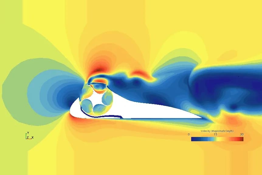
In this project we ran a computational fluid dynamics (CFD) study of the Ahmed body in Ansys Fluent with different rear slant angles. Every case used the same inlet conditions, so the only change was the slant geometry. We compared the flow field, the wake, the surface pressure and the drag coefficient to see how rear-end shape drives aerodynamic performance, which matters for reducing pressure drag and improving fuel efficiency in real vehicles.
Objectives
How we set up the Ahmed body CFD model
The model was built so that the slant angle could be changed while everything else stayed the same, giving a fair comparison between the cases.
Parametric geometry
A clean 3D model of the Ahmed body with parametric control over the rear slant angle.
Mesh
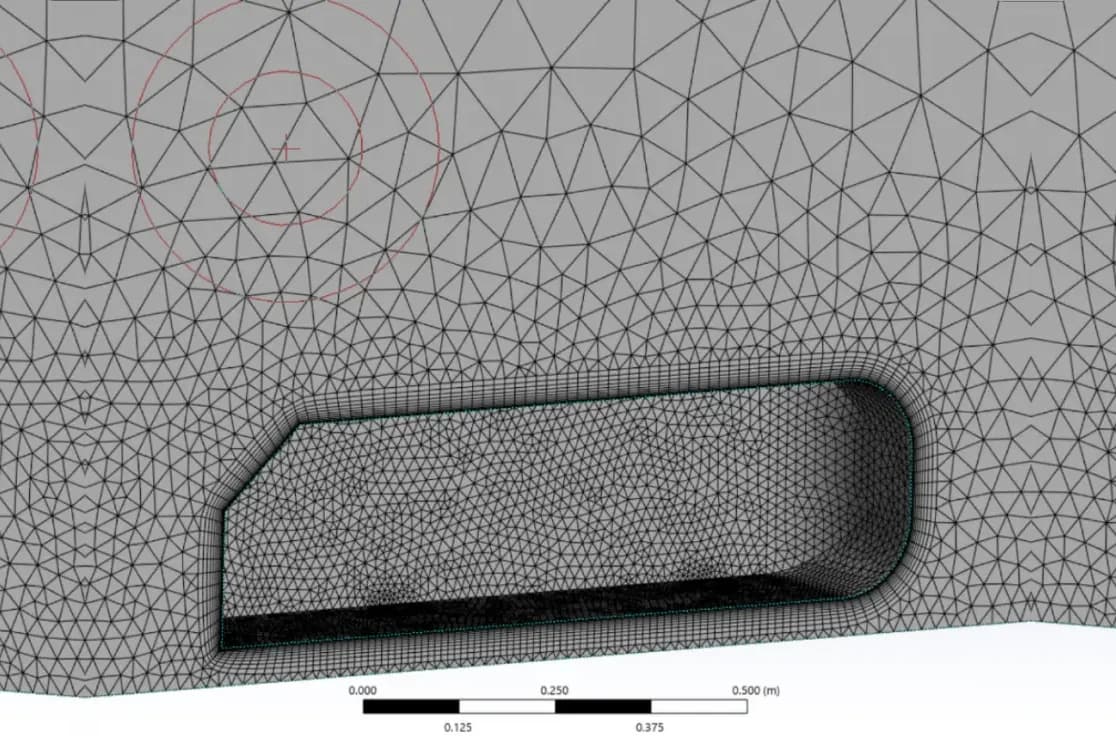
A fine mesh with refined regions near the walls and in the wake, where the flow separates and recirculates.
Flow conditions
Steady-state, incompressible flow with a uniform velocity inlet and a pressure outlet, in a domain sized to keep blockage and wall effects small.
Turbulence model
The realizable k-ε model with enhanced wall treatment, to resolve the near-wall flow accurately.
Slant angle runs
Simulations in Ansys Fluent at 25°, 30°, 35° and 40°, then a comparison of the results across the four cases.
Simulation conditions
| Setting | Value | Notes |
|---|---|---|
| Fluid | Air | At standard atmospheric pressure and temperature |
| Flow | Steady, incompressible | Turbulent external flow over the body |
| Reynolds number | 1–2 million | Representative of scaled vehicle conditions |
| Boundaries | Velocity inlet, pressure outlet | Uniform velocity at the inlet |
| Walls | No-slip | Applied to all body surfaces |
| Turbulence model | Realizable k-ε | With enhanced wall treatment |
| Slant angles | 25°, 30°, 35°, 40° | From attached to fully separated flow |
The Reynolds number compares the inertia of the flow with its viscosity, and it decides whether the boundary layer stays laminar or turns turbulent. To work it out, with the flow regime, for your own speed, size and fluid, try our free Reynolds number calculator.
Results: how the slant angle changes the flow
The four cases cover the change from attached to separated flow over the rear slant:
| Slant angle | Flow over the slant | Wake and drag |
|---|---|---|
| 25° | Mostly attached | Relatively low drag and a stable wake |
| 30° | Mostly attached | Relatively low drag and a stable wake |
| 35° | Partly separated | Wider wake and a noticeable rise in pressure drag |
| 40° | Fully separated | A large recirculation bubble and a much higher drag coefficient |
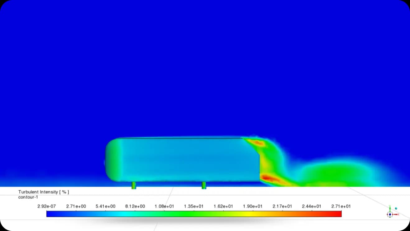
In these simulations the drag coefficient rose non-linearly with the slant angle: once the flow separated from the slant, the wider wake and lower pressure behind the body dominated the aerodynamic response.
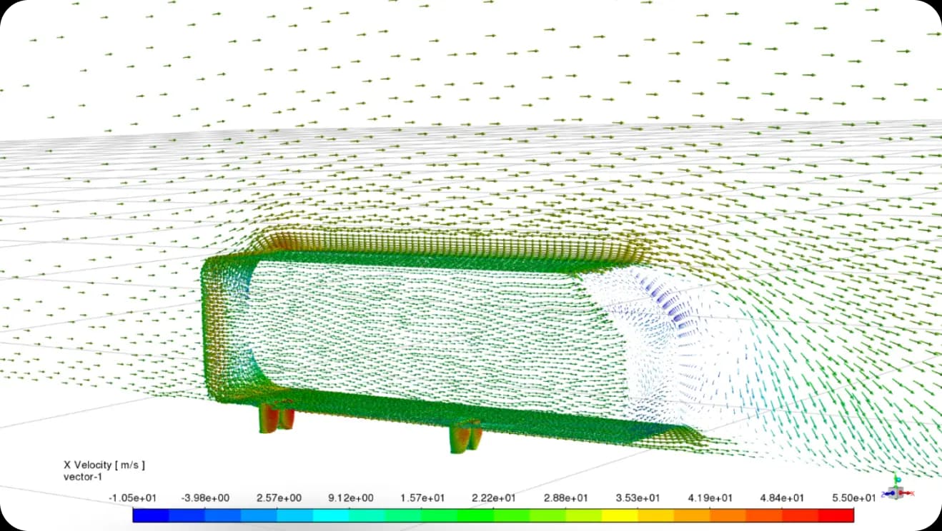

What it means for vehicle design
Small changes to the rear of a vehicle can move it from attached to separated flow, with a large effect on the wake and the drag. A parametric CFD study like this one shows where that change happens before any wind tunnel or prototype work, so the rear-end shape can be chosen for lower drag from the start.
Frequently asked questions
What is an Ahmed body and why is it used in CFD?
The Ahmed body is a simplified car shape with a rounded front, a box-like middle and a slanted rear. It keeps the main flow features of a real vehicle, such as separation over the rear and a turbulent wake, so it is widely used as a benchmark for vehicle aerodynamics and for checking CFD methods.
Which slant angles and flow conditions were simulated?
Slant angles of 25°, 30°, 35° and 40°, all with the same inlet conditions: steady, turbulent, incompressible air flow at standard atmospheric conditions, a Reynolds number of 1–2 million, a uniform velocity inlet, a pressure outlet and no-slip walls.
What happens to the flow as the slant angle increases?
At 25° and 30° the flow stayed mostly attached to the slant, with a stable wake. At 35° it partly separated and the pressure drag rose noticeably, and at 40° it separated completely, forming a large recirculation bubble in the wake.
Which software and turbulence model were used?
Ansys Fluent, with the realizable k-ε turbulence model and enhanced wall treatment, on a mesh refined near the walls and in the wake.