
Home / Projects / CFD of a Toroidal Swirl Separator to Catch Dust and Flies at Outdoor Dining
CFD of a Toroidal Swirl Separator to Catch Dust and Flies at Outdoor Dining
Outdoor dining has one persistent enemy: dust and flies. This project is the CFD behind a device built to deal with exactly that, a toroidal swirl separator that pulls air in, spins it hard, and uses that spin to fling the heavier stuff, dust, large particles, and flies, outward and away, while cleaner air passes on through. It works on the same principle as an industrial cyclone, wrapped into a compact, ring-shaped unit that can sit on or near a table.
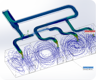

The whole idea lives or dies on the swirl, and swirl is invisible, so it was studied with CFD in SolidWorks Flow Simulation. The model traces the flow as it moves through the separator, showing how fast the air travels and how tightly it rotates. That is what decides whether the device can throw a fly or a dust grain out of the airstream, and it is far cheaper to see it on screen than to build unit after unit and test each one.
The Idea: A Swirl Separator for Dust and Flies
A cyclone separator has no filter and no moving screen to clog. It simply spins the air, and physics does the rest: anything denser than air, a dust particle or a fly, cannot follow the tight curve of the spinning flow, so it is thrown outward to the wall and drops out, while the lighter, cleaner air escapes through the middle. This design takes that idea and folds it into a toroidal, ring-shaped body so it can work as a tabletop or nearby unit for outdoor dining.
The objectives for the CFD were straightforward:
- Show that the geometry actually generates a strong, organised swirl rather than messy, weak flow.
- Map how fast the air moves through the separator and where it moves fastest.
- Confirm the flow path spins the air enough to push heavier particles and flies toward the outer wall.
- Give a visual, animated picture of the device working that can guide the next round of the design.
CFD Setup in SolidWorks Flow Simulation
The separator was analysed in SolidWorks Flow Simulation, which sits directly inside the CAD model and is well suited to internal air flows like this one. Rather than a single still frame, the study was set up to trace the flow all the way through the device and to animate it, so the swirl could be watched as it develops. The key points were:
- Tool: SolidWorks Flow Simulation, run on the toroidal separator geometry with air as the working fluid.
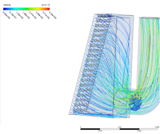
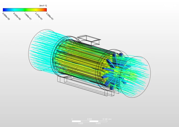
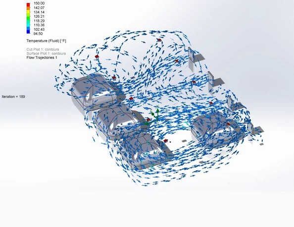
- Result type: flow trajectories, which follow paths of air through the separator and colour them by velocity.
- The solution was run out over its iterations until the flow pattern had settled into a steady, repeating swirl.
- The output was captured both as still images and as an animation of the moving flow.
Flow trajectories are the right tool for a separator, because separation is all about the path each parcel of air takes. If the paths spiral tightly around the device, the swirl is strong and particles get thrown out. If they wander straight through, the device is not doing its job. The trajectories show which of those is happening at a glance.
Swirling Flow and Velocity Results
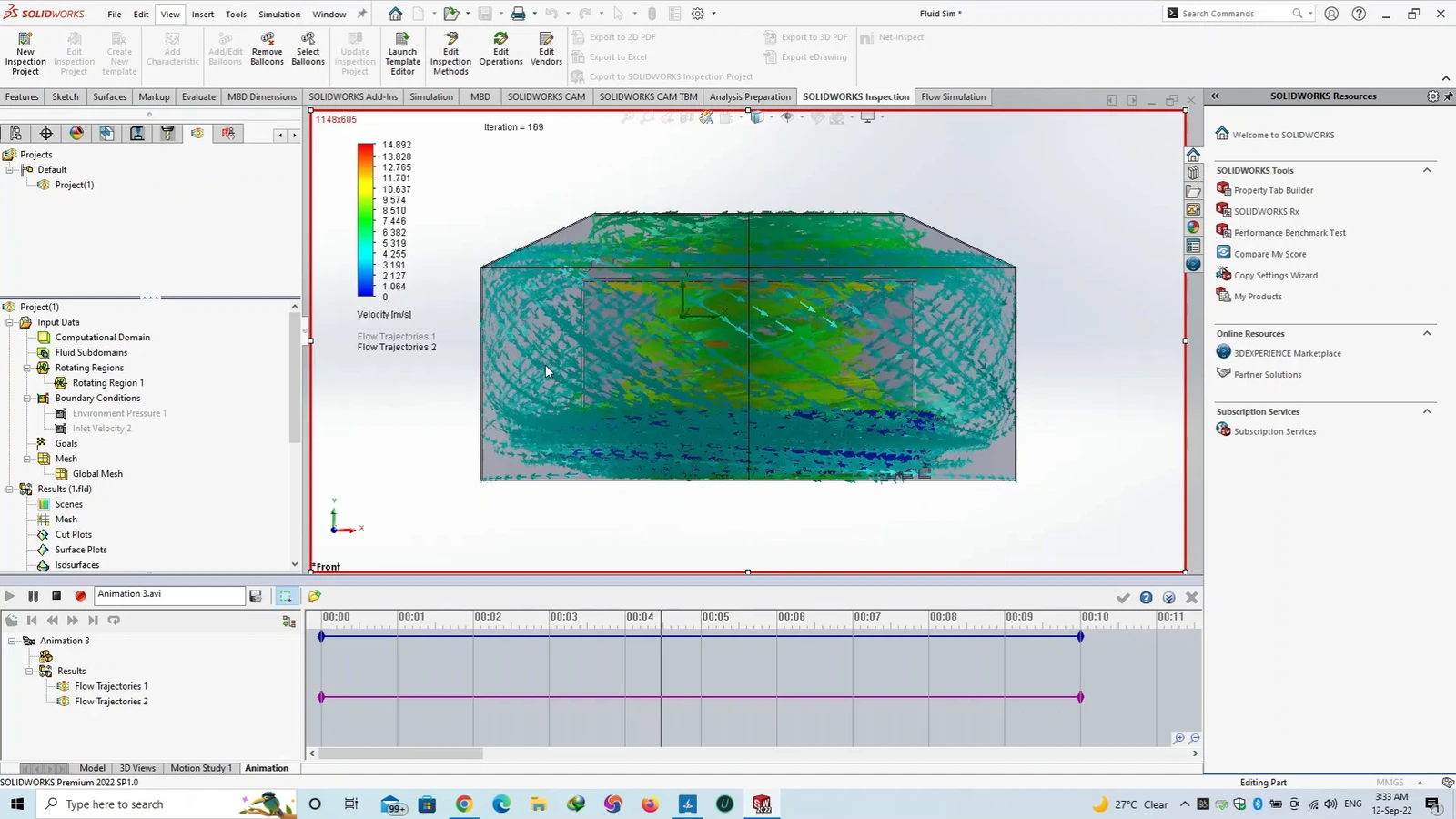
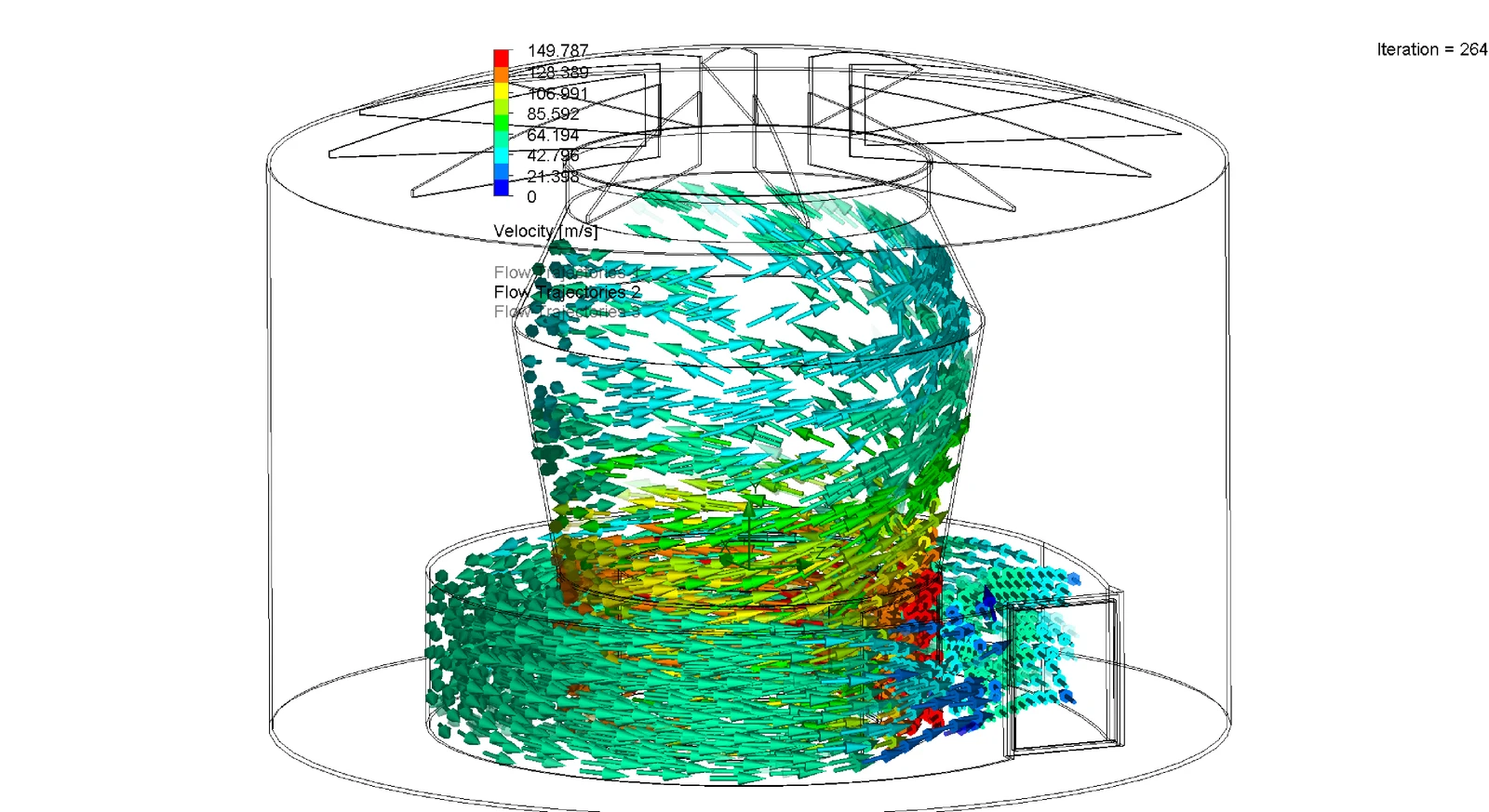
The results show exactly the behaviour the design needs. The flow enters and immediately begins to rotate, forming a clear spiralling column of air that winds its way through the toroidal body. This is the organised swirl that a separator depends on, and the trajectories wrap tightly rather than passing straight through, which is the sign that the geometry is turning the flow the way it should.
The colours map the velocity, and the flow covers a wide range. It is gentle and slow through much of the volume in the cool blues and greens, and then accelerates sharply to its highest speeds, up to roughly 150 m/s, in the tightest, most active part of the swirl near the vanes. That jump in speed is important: the faster and tighter the rotation, the stronger the outward push on any dust or fly caught in the flow, and the more effectively they are separated from the air.
Reading the fast, tightly wound core against the slower outer flow gives a clear picture of where the separator does its work, and confirms that the spin is strong enough in the right places to drive particles and flies toward the wall.
Geometry of the Toroidal Separator
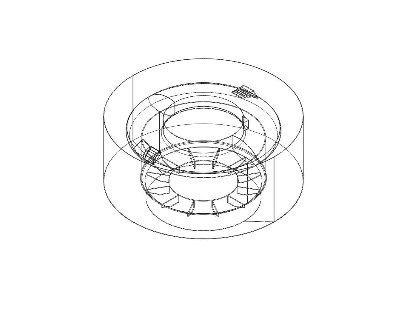
The shape is what creates the swirl. The separator is built around a ring-shaped, toroidal chamber with a set of vanes and a central passage that force the incoming air to turn and rotate instead of flowing straight. The outline below shows the arrangement, with the outer body, the inner ring, and the vanes that give the flow its spin.
With the geometry and the flow understood together, the design has a solid starting point. The same model can now be used to test changes cheaply, such as adjusting the vane angle, the inlet size, or the proportions of the ring, and see straight away how the swirl and the velocity respond, which is the practical route to improving how much dust and how many flies the device can catch.
Separation and Flow CFD at Solvo Engineers
Separators, cyclones, extractors, and any product that has to move air and clean it all come down to understanding the flow inside them, and that flow is almost impossible to judge by eye. CFD makes it visible, showing the swirl, the velocity, and the paths that decide whether a device separates well or not, which is exactly what a design like this needs before it is prototyped. It turns a good idea into something you can see working and then improve with confidence.
At Solvo Engineers we run CFD in SolidWorks Flow Simulation and Ansys for separators, extraction and ventilation, product airflow, and swirling and rotating flows, alongside our wider CFD and FEA consulting work. If you have a product or a system that moves, cleans, or separates air and you want to understand and improve how it flows, our team can help. Reach out through our contact page and talk it through with a CFD engineer.
Our Projects
See how Solvo Engineers has helped its clients achieve their vision of digital innovation.

Our Technologies
 Contact Us
Get in touch with us