
Home / Projects / HVAC Airflow Analysis of an Office Container for Thermal Comfort and Efficiency
HVAC Airflow Analysis of an Office Container for Thermal Comfort and Efficiency
Project Summary
A client wanted to know whether the HVAC setup inside their office container would actually keep the space comfortable to work in. An office container is a compact, enclosed metal box, so the air does not always spread evenly, and a single badly placed vent can leave one corner cold while another stays warm and stuffy. We ran a computational fluid dynamics (CFD) study in Ansys Fluent to see how the supply air really moves through the space, where it reaches, and how air speed and temperature vary from one part of the container to another.
The point of the analysis was to check thermal comfort and energy efficiency before any ducting was locked in. By simulating the airflow in detail, we could see the circulation pattern, find the areas that were well served and the ones that were being missed, and judge whether the current inlet and outlet layout was doing its job. That gave the client a clear, visual basis for adjusting the HVAC design instead of guessing at vent positions on site.
Objectives and Approach
The main goal was to make sure everyone inside the container sits in a comfortable, evenly conditioned space, and to get there without wasting energy on over-cooling. We set a few clear objectives for the CFD study.
- Map how the supply air travels through the container and where the main circulation forms.
- Find the spots that get too little airflow, since those turn into warm or stuffy dead zones.
- Check how air velocity and temperature spread across the working area, so comfort can be judged from real data rather than assumed.
- Show whether the current inlet and outlet positions deliver even conditions, and where to change them if they do not.
We built a CFD model of the container interior in Ansys Fluent, including the supply and return vents in their real positions. The air was treated as a steady turbulent flow, which is the standard way to capture indoor air movement, and the model accounted for the heat the space picks up from occupants, equipment, and the surrounding walls. The mesh was refined near the vents and along the surfaces where the flow changes quickly, so the circulation and the temperature field would be resolved properly.
Simulation Setup and Boundary Conditions
The study was set up as a steady-state CFD simulation in Ansys Fluent. The main settings and inputs were as follows.
- Solver: steady-state, turbulent airflow modelled with a standard RANS turbulence model, which suits enclosed indoor spaces.
- Inlets: conditioned supply air introduced through the HVAC vents at a set temperature and flow rate.
- Outlets: return and exhaust vents set as pressure outlets so the air could recirculate the way it does in the real container.
- Heat sources: internal gains from people, lights, and equipment, along with heat transfer through the container walls, so the temperature result reflects a real working day.
- Mesh: refined around the vents, corners, and internal surfaces to capture the jets, the recirculation, and the thin layers of slow air along the walls.
With this setup the solution gives the airflow field and the temperature field at the same time. Two views tell most of the story: the streamlines, which show the path the air takes and where it slows down, and the surface contours, which show where warm and cool regions build up across the space.
Results and Findings
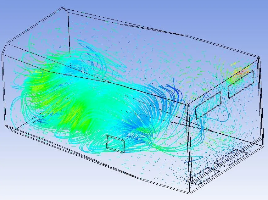
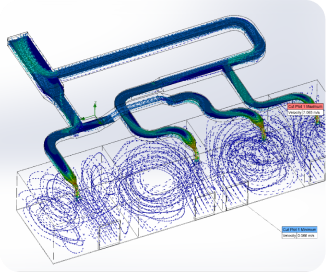
The results showed that the supply air forms one strong circulation loop through the middle of the container, but it does not reach everywhere equally.
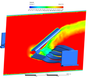

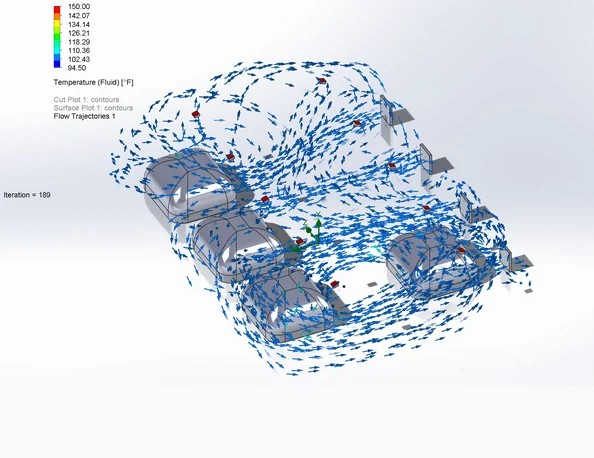
The streamlines make the pattern clear. A fast moving stream of air sweeps through the central zone and drives a large recirculation there, while the far corners and the lower sections see much slower, almost stagnant flow. Those low-flow pockets are exactly where a person would feel the air is stuffy, or where warmth would sit instead of being carried away.
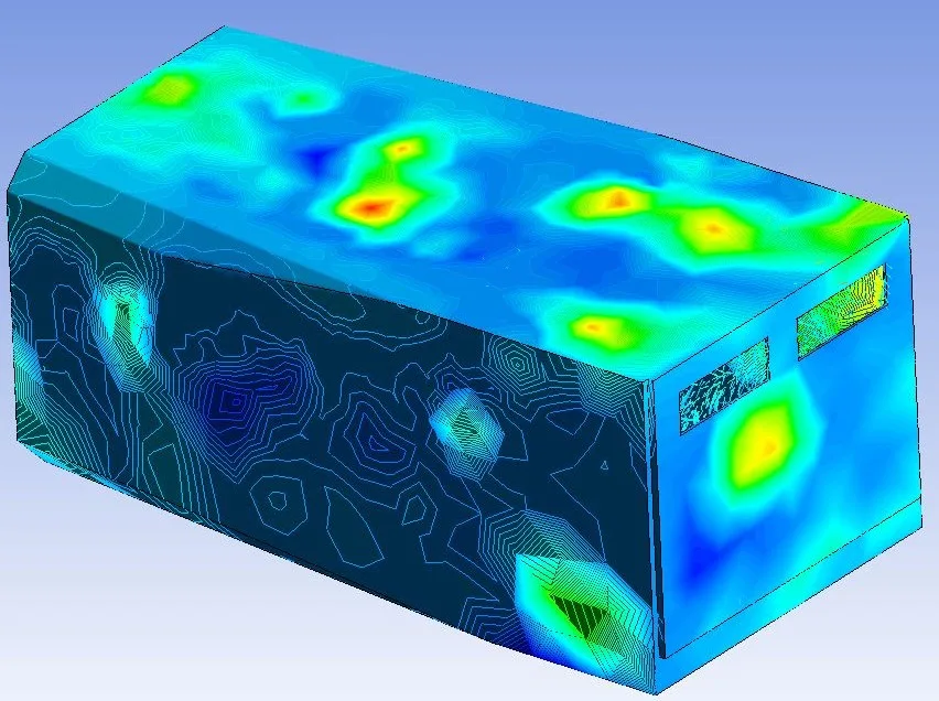
The surface contours back this up. Air speed and temperature are uneven across the container, with active, well-mixed regions near the main jet and slower, warmer patches away from it. In plain terms, the space is comfortable where the air is moving and less comfortable where it is not, so the current vent layout leaves parts of the working area under-served.
The fix is to spread the supply air more evenly. Repositioning or adding a diffuser, splitting the supply so it feeds more than one zone, or adjusting the outlet so it pulls air through the quiet corners all push the circulation into the areas that are currently missed. That evens out temperature and air movement across the whole container, which improves comfort for everyone inside and lets the HVAC unit hold its setpoint without over-cooling the busy zone just to make up for the still ones.
CFD-Driven HVAC Design at Solvo Engineers
Compact, enclosed spaces like office containers, cabins, and modular units are surprisingly hard to condition well, because there is not much room for the air to mix and one badly placed vent can spoil the comfort of the whole space. A CFD study shows exactly how the air behaves before anything is installed, so the ducting, the diffusers, and the size of the unit can be chosen from evidence rather than a rule of thumb. It saves the cost of reworking vents on site and avoids the energy an oversized system wastes when it is fighting poor air distribution.
At Solvo Engineers we use computational fluid dynamics to design and troubleshoot HVAC and ventilation for rooms, containers, cabins, and industrial spaces, covering airflow, thermal comfort, and energy efficiency, and we pair it with structural FEA when a design needs both. If you are working on an HVAC layout, a ventilation problem, or any airflow or thermal question and want to see how it will perform before you build it, our team can help. Reach out through our contact page to talk it through with a CFD engineer.
Related articles
Our Projects
See how Solvo Engineers has helped its clients achieve their vision of digital innovation.

Our Technologies
 Contact Us
Get in touch with us