
Topology Optimization and Design for Manufacturing: Lighter Parts You Can Actually Make

Introduction
Most parts carry more material than they need, added "to be safe" where nobody was sure. Topology optimization asks a better question: for these loads and supports, where does material actually need to be? The answer is often a lighter, stiffer part.
But an optimized shape is only useful if it can be made at a sensible cost. This guide explains how topology optimization works, how to set it up well, and how design for manufacturing (DFM) turns the result into a part you can machine, cast, mould or 3D print.
How Topology Optimization Works
You define a design space (the volume the part may occupy), the loads and supports, an objective (usually maximum stiffness) and a constraint (usually how much material to keep). The most common method, SIMP, gives every element a density between 0 and 1 and repeatedly moves material to where it does the most work, while penalising in-between densities so the result becomes solid or empty.
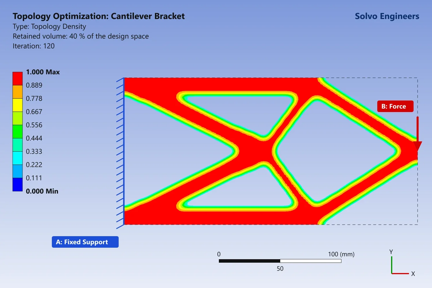
The cover image is a real topology optimization we ran for this article: a 240 × 120 mm cantilever design space, fixed on the left, loaded at the middle of the right edge, keeping 40 % of the material. After 120 iterations the material formed the familiar truss of ties and struts that engineers have long used for cantilevers, found here by the algorithm alone.
Setting Up a Good Optimization
- Keep the interfaces: mark bolt holes, bearing seats and mating faces as non-design regions so they are not removed.
- Include every load case: optimizing for one load produces a part that fails under the others.
- Use realistic supports: over-stiff supports give shapes that will not work in the real assembly.
- Add the right constraints: stress, displacement or natural frequency limits, not just a volume target.
- Add manufacturing constraints: minimum member size, a pull direction for casting or moulding, extrusion, symmetry, or overhang limits for 3D printing. Ansys Mechanical and other tools include these.
From Optimized Shape to Buildable Part
The raw result is a guide, not a finished design. Engineers redraw it in CAD with smooth surfaces, standard features and sensible thicknesses for the chosen process:
- CNC machining: pockets the tool can reach, inner radii that match standard cutters, no very deep narrow pockets, and flat datum faces for fixturing.
- Casting: even sections without isolated thick spots (which cause porosity), draft and generous radii.
- Injection molding: uniform walls, ribs and draft, as described in our guide to plastic part design for injection molding.
- Sheet metal: bends, flanges and embossed ribs instead of organic shapes.
- Metal 3D printing: organic shapes are welcome, but overhangs beyond roughly 45° need supports, internal powder must be able to escape, and critical faces are usually machined afterwards.
Design for Manufacturing Checklist
- Fewer parts: combine parts where the process allows.
- Standard features, hole sizes and fasteners.
- Tight tolerances only where the function needs them.
- Materials that suit the process and the volume.
- Easy assembly: one assembly direction, self-locating parts and access for tools (design for manufacture and assembly, DFMA).
Validate the Final Design
The redrawn part is checked with a full FEA, because smoothing and DFM changes alter the stresses. Slender members created by the optimization also need a buckling check, and parts under repeated loads need a fatigue check. Our guide to static structural analysis in Ansys Workbench covers how to run and check these analyses.
Where the Savings Come From
Weight savings depend on how conservative the original design was, and can reach tens of per cent. FEA results usually point to them clearly:
- In our FEA of an industrial fixture, the peak stress of 146.8 MPa against a yield strength above 250 MPa showed clear room to remove material.
- In our FEA of a battery module frame, only one small region dropped to a safety factor of about 0.41, so local reinforcement there beat thickening the whole frame.
- In our FEA of a beam bracket, the deformation plot showed which areas work hard and which barely move, exactly the information an optimization uses.
What We Need to Start
- 3D CAD of the current part and its surroundings, or drawings for our 3D CAD team to model.
- All load cases, supports and interfaces that must stay.
- The manufacturing process and material you plan to use.
- Your targets: weight, stiffness, stress or frequency limits.
Frequently Asked Questions
Is topology optimization the same as generative design?
They are closely related. Generative design tools usually run many optimizations with different manufacturing constraints and materials, and offer several design options to choose from.
Can an optimized part be machined, or only 3D printed?
With manufacturing constraints and a DFM redesign, optimized parts are regularly machined, cast and moulded. 3D printing simply allows the most freedom.
Does lighter mean weaker?
Not when it is done properly: material is removed where it does little work, and the final design is validated against the same strength and stiffness targets.
Which software do you use?
We work mainly in Ansys, and choose the tool that suits the part, the process and your existing workflow.
How do we get a quote?
Send your CAD files, loads and manufacturing process through our contact page. We will reply with a scope, timeline and quote.
Make Your Parts Lighter Without the Risk
Our engineers can find the material your part does not need, redesign it for your manufacturing process and validate the result with FEA. Send us your CAD files and requirements, and we will reply with a clear scope and quote.