
Fatigue Analysis of Welded Machine Frames: How to Stop Cracks Before They Start

Introduction
Welded frames carry presses, conveyors, cranes, robot bases and mobile machinery. They are designed to be strong, and on paper they are. Yet months or years into service a crack appears at a weld, grows, and eventually takes the machine out of production.
That is fatigue, and it is the most common way welded structures fail. The good news is that it is predictable. Fatigue analysis with Finite Element Analysis (FEA) shows which welds are at risk, how long they will last under your real loads, and which design changes will stop the cracks before they start.
Why Welds Are the Weak Spot
Welded joints have much lower fatigue strength than the plain steel around them, for three reasons:
- Geometry: the weld toe is a sharp notch that concentrates stress.
- Residual stress: welding leaves tensile stresses in and around the weld that can be close to the yield strength.
- Small defects: undercut, porosity and lack of fusion act as ready-made crack starters.
One practical consequence surprises many designers: the fatigue strength of an as-welded joint barely depends on the grade of steel. Switching to a higher-strength steel will not fix a weld detail that is cracking.
Why Static Strength Is Not Enough
A frame can stay well below its yield strength and still crack. Fatigue depends on the stress range each cycle and on the number of cycles, not on the peak stress alone, and machines often see millions of cycles over their life.
That is why a static check, like our FEA of a beam bracket for structural integrity, is the starting point, and a fatigue check is the next step for any welded part that is loaded again and again.
How Weld Fatigue Analysis Works
- Loads: define the load cases and the duty cycle, meaning how often each load occurs over the life of the machine.
- Stresses: FEA calculates the stresses at each weld detail for every load case.
- Stress ranges: for varying loads, rainflow counting turns the load history into a set of stress ranges and cycle counts.
- Life: each weld detail has an S-N curve (its fatigue class), and Miner's rule adds up the damage from all the cycles to predict the life.
Three established methods are used to assess the welds:
- Nominal stress: compares the stress in the member with the detail categories of standards such as EN 1993-1-9 (Eurocode 3) or BS 7608.
- Hot-spot stress: extrapolates the structural stress to the weld toe from the FEA results, following the IIW recommendations. It works well for complex joints where no standard detail fits.
- Effective notch stress: models the weld toe and root with a small reference radius (1 mm in the IIW method) for the most detailed assessment.
Getting the Loads Right
A fatigue prediction is only as good as the loads behind it. The most reliable sources are:
- The machine's operating cycle: loads, speeds and the number of cycles per hour, shift and year.
- Strain gauge measurements on an existing machine, which capture the real load history including shocks and starts and stops.
- Motion and process data, such as cutting, pressing or drilling forces.
Repetitive operations are exactly where fatigue matters; in our structural analysis of a 6-DOF robotic drilling arm, the repeated drilling load is what makes a fatigue check on the peak-stress areas worthwhile.
Design Changes That Stop Cracks
Fatigue life is very sensitive to the stress range, so modest changes at the right place can extend it many times over:
- Move welds away from high-stress areas, such as the ends of beams and the corners of openings.
- Avoid ending stiffeners and gussets abruptly; taper them and keep weld ends away from the highest stress.
- Use full-penetration welds where the root would otherwise be loaded, and avoid intermittent welds in fatigue-loaded areas.
- Reinforce local hot spots instead of making the whole frame heavier.
- Improve existing welds with toe grinding, TIG dressing or high-frequency mechanical impact (HFMI) treatment, as covered by IIW guidance.
Stress tends to build at weld lines, bolt holes and cut-out edges, which is exactly what our FEA of a battery module frame looked at before pinpointing where the frame needed reinforcement.
Residual Stress and Distortion from Welding
Welding heat does more than join parts: it leaves residual stresses and pulls the frame out of shape as it cools. Thermal and structural simulation of the welding heat input predicts this distortion and helps choose a welding sequence and fixturing that keep the frame straight. The heat-source modelling is the same as in our transient thermal analysis of a laser heat source on a plate.
Fixing a Frame That Is Already Cracking
- Find the root cause: compare the crack location with the FEA hot spots and check whether the real loads are higher than assumed.
- Design the fix: test repair and reinforcement options on screen before any welding is done.
- Plan inspection: the analysis shows which welds to inspect, and how often, until the fix is in place.
Frequently Asked Questions
Which standards do you use for weld fatigue?
Usually the IIW recommendations and EN 1993-1-9 (Eurocode 3), BS 7608, or the standard your industry or customer requires.
Do we need strain gauge measurements?
They are not essential, but they make the prediction much more reliable. Without them we build the load spectrum from your duty cycle and state the assumptions clearly.
Can you assess a frame that has already cracked?
Yes. We model the frame, match the analysis to the crack location and test repair options before you weld anything.
How do we get a quote?
Send your CAD files, weld details and a short description of the loads through our contact page. We will reply with a scope, timeline and quote.
Stop Weld Cracks Before They Stop Your Machine
Whether you are designing a new frame or dealing with cracks in service, our engineers can predict weld fatigue life and show you exactly which changes will make the frame last. Send us your CAD files and loads, and we will reply with a clear scope and quote.
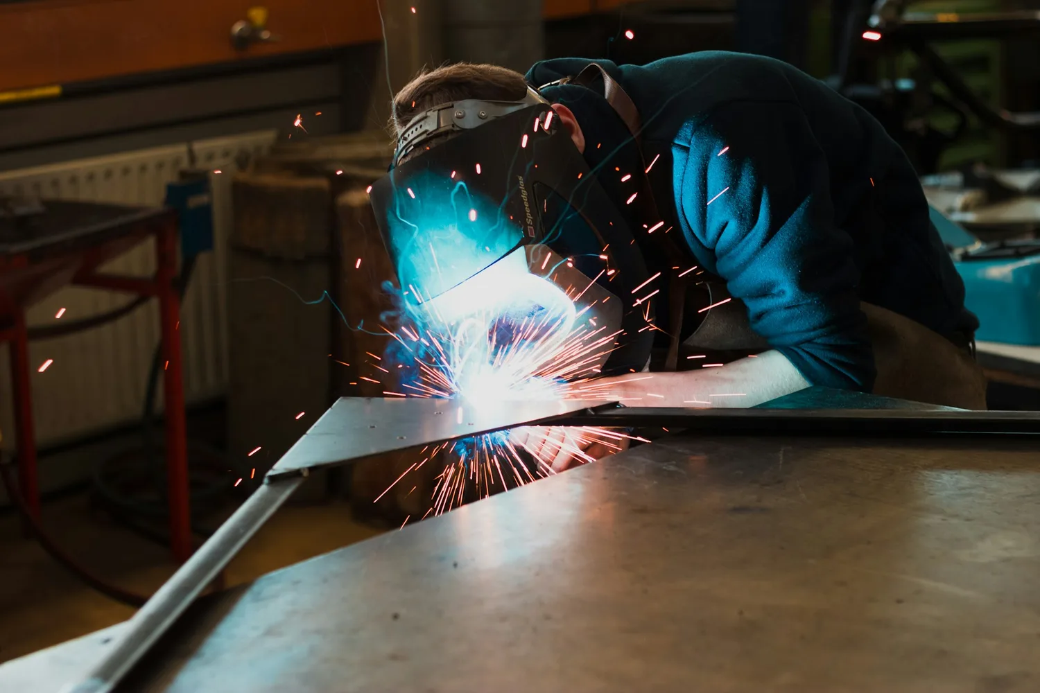
Cover photo: Maxime Agnelli on Unsplash